Correct as at 20th April 2024. It may be superseded at any time.
Extract taken from: Vehicle Inspection Portal > VIRMs > Alternative fuel system certification > CNG inspection
CNG inspection
2-1 Alternative Fuel System Installation Certificate
Reason for rejection
Mandatory equipment
1. A vehicle fitted with an alternative fuel system in working order does not have an Alternative Fuel System Installation Certificate (Note 1) (Note 2) (Figure 2–1–1).
2. A CNG fuel system fitted to a vehicle does not comply with an applicable standard specified in Table 2-1-1.
3. A vehicle fitted with a CNG alternative fuel system to NZS: 5422: 1987 does not have an identification plate displaying:
a) the text ‘CNG’, or
b) the identification number of each cylinder, or
c) the date of installation, or
d) the water capacity of the total installation, or
e) the date of the last retest, or
f) the vehicle registration number.
4. A vehicle fitted with a CNG alternative fuel system to AS/NZS 2739 does not have a CNG compliance plate securely attached to the body work in the engine bay in a clearly visible location.
5. The installation certificate or identification plate or compliance plate (Figure 2–1–2):
a) does not match the vehicle, or
b) does not match the alternative fuel system fitted to the vehicle, or
c) is not legible, or
d) is not valid.
Note 1
Installation certificates are prescribed by the NZ Transport Agency (including its predecessors). The most recent certificate is provided in Sample certification documents.
Note 2
Where no original installation certificate can be produced, a new installation certificate must be issued.
Table 2-1-1. LPG standards requirements
| Date the LPG System was fitted | |
|---|---|
|
Before 1 July 2005 |
On or after 1 July 2005 |
|
Must comply with:
|
Must comply with:
|
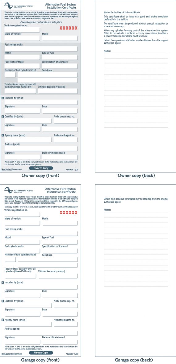
Figure 2-1-1. Alternative Fuel System Installation Certificate (MOT 4069)
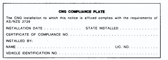
Figure 2-1-2. CNG Compliance plate
Summary of legislation
Applicable legislation
- Land Transport Rule: Vehicle Standards Compliance 2002
- AS/NZS 2739: 2003, section 6.9.
Mandatory equipment
1. A vehicle that is fitted with an alternative fuel system in working order must have an Alternative Fuel System Installation Certificate before it is issued with an Alternative Fuel Inspection Certificate.
2. The alternative fuel system must match the installation certificate and fully comply with the requirements of TR76 and any approval granted under them.
3. A CNG fuel system installed in a vehicle must comply with an applicable CNG fuel system standard as specified in Table 2-1-1 (Note 3).
4. A vehicle fitted with a CNG alternative fuel system to NZS: 5422: 1987: Part 2 must have an identification plate installed near the refuelling connection clearly visible to the refueller displaying ‘CNG’, the cylinder identification numbers, the date of installation, the water capacity of the total installation, the date of the last retest and the vehicle registration number.
5. A vehicle fitted with a CNG alternative fuel system to AS/NZS 2739 must have a CNG compliance plate securely attached to the body work in the engine bay in a clearly visible location.
2-2 Vehicle Identification labels
Reasons for rejection
Mandatory equipment
1. An identification label as shown in Figure 2-2-1 is not affixed as close as practicable to each of the vehicle’s registration plates.
Condition
2. A required plate label or notice:
a) is illegible, or
b) has unauthorised alterations.
Note 1
AS/NZS 2739: 2003 specifies a red circle for Australia. Vehicles fitted with red circles may retain these, but must also be fitted with the white diamonds specified above.
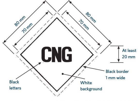
Figure 2–2–1. CNG vehicle identification label
Summary of legislation
Applicable legislation
- NZS 5422: 1987, Part 1, section 7.1
- AS/NZS 2739: 2003, section 6.9 and 7.4
- Land Transport Rule: Vehicle Standards Compliance 2002
- Land Transport Rule: Vehicle Equipment 2004.
Mandatory equipment
1. An identification label as shown in Figure 2-2-1 must be affixed as close as practicable to each of the vehicle’s registration plates.
2-3 Cylinder
Reason for rejection
Condition
1. The cylinder’s test date and cylinder testing station identification mark:
a) are missing, or
b) are not legible, or
c) have been altered, or
d) have not been stamped on the container.
2. There are more than five years between the test date stamped on a cylinder and the date of the next alternative fuels inspection.
3. A cylinder shows evidence of impact damage, corrosion, or heating by fire.
Note 1
Cylinder means a pressure vessel, or gas cylinder for the storage of CNG to be used as fuel for an engine.
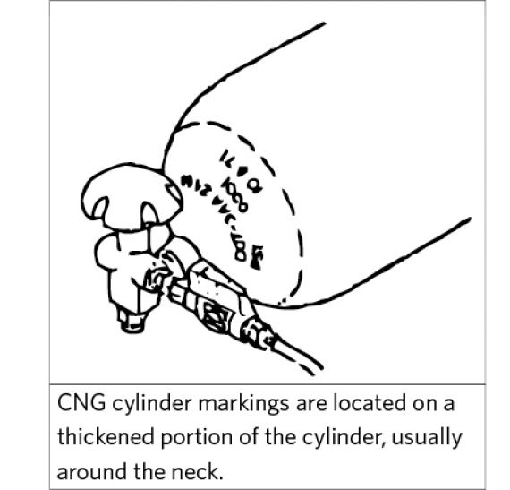
Figure 2-3-1. Cylinder markings
Summary of legislation
Applicable legislation
- AS/NZS 2739: 2003, section 6.9.
Condition
1. The cylinder must be stamped with the test date and the identification mark of the cylinder testing station.
2. The date stamp on a cylinder must be within five years of the next alternative fuels inspection.
3. A cylinder must not show evidence of impact damage, corrosion, or heating by fire.
2-4 Cylinder attachment
Reason for rejection
Condition
1. The security of the container attachment has been affected or weakened by:
a) rust, corrosion, abrasion or impact damage, or
b) loose nuts, worn of stretched bolts, or
c) loose bands, wear under bands, incompatible band materials, or
d) cracks or metal fatigue.
Summary of legislation
Applicable legislation
- AS/NZS 2739: 2003, section 6.9.
Condition
1. A cylinder attachment must not have any of the following conditions such that the security of the attachment is at risk:
a) rust, corrosion, abrasion or impact damage
b) loose nuts, worn of stretched bolts
c) loose bands, wear under bands, incompatible band materials
d) cracks or metal fatigue.
2-5 Fuel system components
Reasons for rejection
Mandatory equipment
1. An item listed in Table 2-5-1 is missing.
2. An installation to AS/NZS 2739: 2003 does not have a refuelling information plate which includes the next cylinder retest date or does not have this information on the compliance plate in the engine bay.
3. An installation to NZS 5422: 1987, Part 2 does not have a permanent label near the service isolation valve with the wording CNG SERVICE SHUT-OFF VALVE or similar and a clear indication of the CLOSED and OPEN positions.
Condition
4. A component is not in good working condition.
5. The refuelling connection is dirty.
6. The refuelling connection dust plug or cap is:
a) missing, or
b) not securely attached, or
c) not held captive by a strap or similar device where it would be practicable to do so.
Performance
7. A manual valve cannot be operated without the use of tools.
8. The automatic fuel shut-off device allows CNG to flow to the engine when it is not running (Note 2).
9. The starter motor can be operated when the refuelling interlock device micro-switch is operated (Note 3).
Note 1 Definitions:
Non-return valve means a valve which permits fuel flow in only one direction.
Automatic fuel shut-off device means a provision for shutting off the fuel supply unless certain essential conditions exist.
Refuelling interlock device means a system used to control the delivery pressure of gaseous fuel to the engine.
Note 2
Automatic fuel shut-off devices can normally be heard operating. They can be made to operate in a number of ways:
a) Electrically operated valves may be operated by cutting the power supply to them. Turning the fuel selector knob to a
non-CNG fuel (petrol or diesel) will cut the power supply.
b) Valves will open when the ignition is turned on, and will then close if the engine is not cranked.
c) Vacuum-operated valves can be activated by disconnecting the appropriate hose.
Note 3
The interlock device micro-switch can usually be operated with a finger.
Table 2-5-1. Mandatory equipment for a CNG fuel supply system (Note 1)
|
|
|
Summary of legislation
Applicable legislation
- Land Transport Rule: Vehicle Standards Compliance 2002
- Land Transport Rule: Vehicle Equipment 2004
- AS/NZS 2739: 2003, section 6.9.
Mandatory equipment
1. The fuel supply system must include the items in Table 2-5-1.
2. Installations to NS/NZS 2739: 2003 must have a refuelling information plate which includes the next cylinder retest date. (This may be combined with the compliance plate on vehicles with the refuelling connection in the engine bay.)
3. Installations to NZS 5422: 1987, Part 2 must have a permanent label near the service isolation valve with the wording CNG SERVICE SHUT-OFF VALVE or similar and a clear indication of the CLOSED and OPEN positions.
Condition
4. All fuel system components must be in safe working condition.
5. The refuelling connection must:
a) be free of foreign matter, and
b) have a dust plug or cap that is:
i. captive, where practicable, and
ii. securely attached.
Performance
6. All manual valves must operate without the necessity for tools.
7. An automatic fuel shut-off device must operate when the engine is not running.
8. The refuelling interlock device must cut the power to the starter motor when the refuelling nozzle is engaged.
2-6 Cylinder compartment
Mandatory equipment
1. A cylinder is located within the body shell of the vehicle and no compartment or sub-compartment is fitted that (Note 1):
a) encloses the valves, fittings and pipe connections associated with the cylinder, and
b) it is vented to the atmosphere.
Condition
2. The compartment structure, joints, conduit connections or pipe bulkhead seals are deteriorated, damaged, kinked or punctured so that gas may leak or gas flow through a vent could be constricted.
3. The compartment or sub-compartment is not gastight (Note 2).
Note 1
Cylinder compartment means a structure of rigid or pliable material which encloses the whole of the cylinder and its fittings, whose purpose is to collect any gas leakage which might occur, so that it can be discharged to open air. A car boot is not an acceptable compartment.
Cylinder sub-compartment means a structure of rigid or pliable material which encloses the cylinder fittings, whose purpose is to collect any gas leakage which might occur, so that it can be discharged to open air.
Note 2
AS/NZS 2739: 2003, section 6.8.2 describes a standard gastight test.
Summary of legislation
Applicable legislation
- Land Transport Rule: Vehicle Standards Compliance 2002
- Land Transport Rule: Vehicle Equipment 2004
- AS/NZS 2739: 2003, section 6.9.
Mandatory equipment
1. Where a cylinder is located within the body shell of the vehicle, either the:
a) whole of the cylinder and its attached components and fittings must be enclosed in a compartment that is vented to the atmosphere, or
b) valves, fittings and pipe connections associated with or attached to the container must be enclosed in a sub-compartment attached to the container and vented to the atmosphere.
Condition
2. The compartment structure, joints, conduit connections and pipe bulkhead seals must not be deteriorated, damaged, kinked or punctured so that gas may leak or gas flow through a vent could be constricted.
3. The compartment or sub-compartment must be gastight.
2-7 Location and ground clearances
Reasons for rejection
Mandatory equipment
1. An installation to NZS 5422: 1987, Part 2 does not meet all the requirements in the left-hand column of Table 2-7-1.
2. An installation to AS/NZS 2739: 2003 does not meet all the requirements in either:
a) the right-hand column of Table 2-7-1, or
b) the left-hand column of Table 2-7-1 of the requirements
Table 2-7-1. Location and ground clearance requirements
|
Requirements from NZS 5422: 1987: Part 2 |
Requirements from AS/NZS 2739: 2003 |
|---|---|
|
1. Cylinders, fittings and pipework must be mounted inside the perimeter of the vehicle. 2. Cylinder valves on externally mounted containers must be positioned no less than 200mm from the vehicle extremities. 3. A cylinder must not be fitted: a) on the roof or above a passenger compartment b) forward of the rear of the driver’s seat in its rearmost position without specific approval c) in a position beneath the vehicle that decreases the effective ground clearance. 4. A cylinder located between or behind the axles must be within the zone limit shown in Figure 2-7-1. |
1. A cylinder must lie within the ground clearance zone limits indicated by Table 2-7-2 and Figure 2-7-2 and Figure 2-7-3. 2. A cylinder must not be mounted outside the body contour to the front or sides of the vehicle. 3. A cylinder must not be mounted outside the body contour to the rear or top of the vehicle without specific approval. 4. A cylinder must be located such that its fittings are at least 100mm inside the outer body skin or tray of the vehicle. |
Table 2-7-2. Ground clearance zone limits (requirements from AS/NZS 2739: 2003)
|
Vehicle mass1 |
Chassis ground clearance at rear of vehicle |
Figure that shows ground clearance zone limits |
|---|---|---|
|
Less than 3500kg |
610mm or less |
Figure 2-7-2 |
|
Less than 3500kg |
More than 610mm |
Figure 2-7-3 |
|
3500kg or more |
610mm or less |
Figure 2-7-2 |
|
3500kg or more |
More than 610mm |
Figure 2-7-3 |
1 Unladen mass with fuel, coolant and oil containers full.
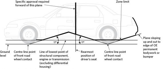
Figure 2-7-1. Zone limit for container location (requirements from NZS 5422: 1987, Part 2)
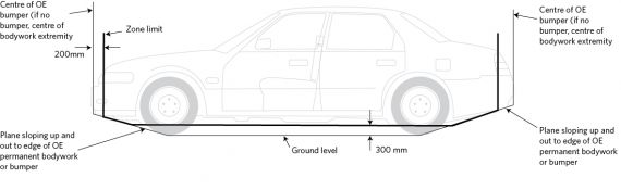
Figure 2-7-2. Ground clearance zone limits for a small vehicle (requirements from AS/NZS 2739: 2003)
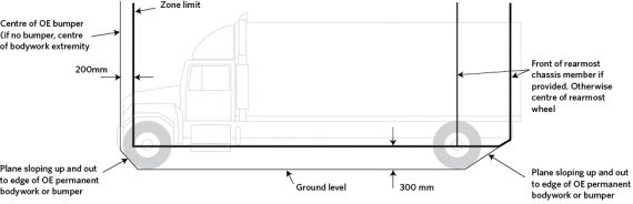
Figure 2-7-3. Ground clearance zone limits for a large vehicle (requirements from AS/NZS 2739: 2003)
Summary of legislation
Applicable legislation
- Land Transport Rule: Vehicle Standards Compliance 2002
- Land Transport Rule: Vehicle Equipment 2004
- AS/NZS 2739: 2003, section 6.9 and 3.16
- NZS 5422: 1987, Part 2, section 2.3.
Mandatory equipment
1. Installations to NZS 5422: 1987, Part 2 must meet the requirements in the left-hand column of Table 2-7-1.
2. Installations to AS/NZS 2739: 2003 must meet the requirements in the right-hand column of Table 2-7-1, or if this is not practicable, the requirements in the left-hand column.
2-8 Fuel service line
Reasons for rejection
Mandatory equipment
1. A fuel service line enters an enclosed driver, passenger or luggage compartment (Note 1).
2. A fuel service line in a drive shaft tunnel is within 40mm of the drive shaft under some operating conditions.
3. The underside of a fuel service line in a drive shaft tunnel is more than 15mm of the intersection of the drive shaft tunnel and the floor pan.
4. Required fuel line protection is missing.
5. A required clip or grommet is missing.
6. A pipe, component or fitting that is not fully protected by a radiation shield at least 15mm away is within 150mm of a hot object at a temperature above the normal water jacket temperature.
7. A pipe, component or fitting that is fully protected by a radiation shield at least 15mm away is within 40mm of a hot object at a temperature above the normal water jacket temperature (Figure 2-8-1).
Condition
8. A fuel line:
a) shows signs of corrosion damage (Note 2) such as pitting, or
b) is bulging, or
c) is insecure, or
d) is twisted, or
e) is kinked, or
f) shows damage, such as cuts, crimps or abrasions that expose the wire.
Note 1
Fuel service line means the fuel line supplying the engine and running from the cylinder(s) to the engine.
Note 2
Corrosion damage is where the metal has been eaten away, which is evident by pitting. The outward signs of such corrosion damage are typically displayed by the lifting or bubbling of paint. In extreme cases, the area affected by the corrosion damage will fall out and leave a hole.
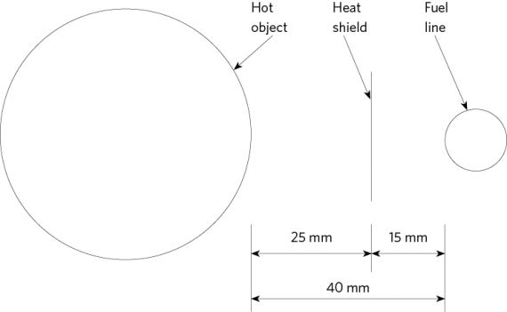
Figure 2-8-1. Minimum fuel line distance to hot object with heat shield
Summary of legislation
Applicable legislation
- Land Transport Rule: Vehicle Standards Compliance 2002
- Land Transport Rule: Vehicle Equipment 2004
- AS/NZS 2739: 2003, section 6.9.
Mandatory equipment
1. A fuel service line must not enter an enclosed driver, passenger or luggage compartment.
2. A fuel service line in a drive shaft tunnel must not be closer than 40mm from the drive shaft under all operating conditions.
3. The underside of a fuel service line must be within 15mm of the intersection of the drive shaft tunnel and the floor pan.
4. A fuel service line below the body shell must be protected from impact or abrasion.
5. Piping subject to corrosion must be protected throughout its exposed length.
6. Piping must be secured to the chassis frame or body with cushioned clips not more than 600mm apart.
7. A pipe must be protected with a grommet where it passes through a body panel.
8. A pipe, component or fitting that is not fully protected by a radiation shield at least 15mm away, must not be within 150mm of a hot object at a temperature above the normal water jacket temperature.
9. A pipe, component or fitting that is fully protected by a radiation shield at least 15mm away, must not be within 40mm of a hot object at a temperature above the normal water jacket temperature (Figure 2-8-1).
Condition
10. An alternative fuel system in working order must be in a safe working condition.
2-9 System gastightness
Reasons for rejection
Condition and performance
1. With maximum pressure in the system and all pipe connections and valves tested for leaks (with valves in both open and closed positions), a leak is indicated (Note 1).
Note 1
AS/NZS 2739: 2003, Appendix 2 describes leak detection methods.
Summary of legislation
Applicable legislation
- Land Transport Rule: Vehicle Standards Compliance 2002
- Land Transport Rule: Vehicle Equipment 2004
- AS/NZS 2739: 2003, section 6.9.
Condition and performance
1. Pipe and component connections must be gastight with manual valves in both open and closed positions.