Correct as at 20th April 2024. It may be superseded at any time.
Extract taken from: Vehicle Inspection Portal > VIRMs > Alternative fuel system certification > LPG inspection
LPG inspection
1-1 Alternative Fuel System Installation Certificate
Reason for rejection
Mandatory equipment
1. A vehicle fitted with an alternative fuel system in working order does not have an Alternative Fuel System Installation Certificate (Note 1) (Note 2) (Figure 1–1–1).
2. An LPG fuel system fitted to a vehicle does not comply with an applicable standard specified in Table 1-1-1 (Note 3).
3. A vehicle fitted with an LPG alternative fuel system to NZS 5422: 1987 does not have an identification plate installed displaying:
a) the text ‘LPG’, or
b) the identification number of each container, or
c) the date of installation.
4. A vehicle fitted with an LPG alternative fuel system to AS/NZS 1425 does not have an LP gas compliance plate (one for each container) securely attached to the body work in the engine bay in a clearly visible location (Figure 1–1–2).
5. The installation certificate or identification plate or compliance plate:
a) does not match the vehicle, or
b) does not match the alternative fuel system fitted to the vehicle, or
c) is not legible, or
d) is not valid.
Note 1
Installation certificates are prescribed by the NZ Transport Agency (including its predecessors). The most recent certificate is provided in Sample certification documents.
Note 2
Where no original installation certificate can be produced, a new installation certificate must be issued.
Note 3
LPG systems fitted to vehicles in Australia may meet AS/NZS 1425: 1999 if they were installed between 1999 and 2003. This is acceptable, although that version of the standard was never approved for installations carried out in New Zealand.
Note 4
While the LPG system must be installed to the appropriate version of AS/NZS 1425, the installation plate or certificate may not actually specify the version. In that case, the vehicle inspector may assume that the LPG system was installed to the correct version of AS/NZS 1425.
Table 1-1-1. LPG standards requirements
| Date the LPG System was fitted | ||
|---|---|---|
|
Before 1 July 2005 |
Between 1 July 2005 and |
On or after 1 June 2009 |
|
Must comply with:
|
Must comply with (Note 4):
|
Must comply with (Note 4):
|
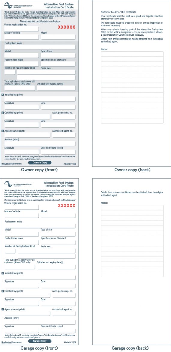
Figure 1-1-1. Alternative Fuel System Installation Certificate (MOT 4069)
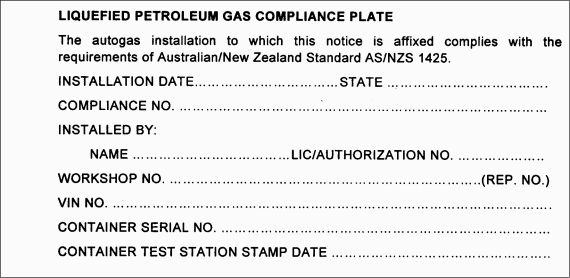
Figure 1-1-2. LPG compliance plate details
Summary of legislation
Applicable legislation
- Land Transport Rule: Vehicle Standards Compliance 2002
- Land Transport Rule: Vehicle Equipment 2004
- AS/NZS 1425: 2003, section 6.9.
Mandatory equipment
1. A vehicle that is fitted with an alternative fuel system in working order must have an Alternative Fuel System Installation Certificate before it is issued with an Alternative Fuel Inspection Certificate.
2. The alternative fuel system must match the details on the installation certificate and fully comply with the requirements of the applicable standard and any approval granted under legislation.
3. An LPG fuel system installed in a vehicle must comply with an applicable LPG fuel system standard as specified in Table 1-1-1 (Note 3).
4. A vehicle fitted with an LPG alternative fuel system to NZS 5422: 1987 must have an identification plate installed preferably in the engine compartment displaying ‘LPG’, the container identification numbers and the date of installation.
5. A vehicle fitted with an LPG alternative fuel system to AS/NZS 1425 Part 1 must have an LP gas compliance plate (one for each container) securely attached to the body work in the engine bay in a clearly visible location.
1-2 Vehicle Identification labels
Reasons for rejection
Mandatory equipment
1. A vehicle is not fitted with identification labels as shown in Figure 1-2-1 positioned in a clearly visible location as close as practical to the front and rear registration plates.
Condition
2. An identification label:
a) is illegible, or
b) has unauthorised alterations.
Note 1
AS/NZS 1425: 2003 specifies a red diamond for Australia. Vehicles fitted with red diamonds may retain these, but must also be fitted with the white diamonds specified above.
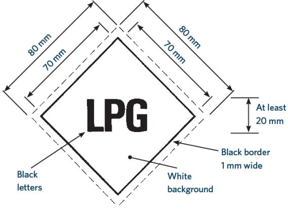
Figure 1-2-1. LPG vehicle identification label
Summary of legislation
Applicable legislation
- Land Transport Rule: Vehicle Standards Compliance 2002
- Land Transport Rule: Vehicle Equipment 2004
- NZS 5422: 1987 Part 1, section 7.1
- AS/NZS 1425: 2003, section 7.4
Mandatory equipment
1. A vehicle must be fitted with identification labels as shown in Figure 1-2-1 positioned in a clearly visible location as close as practicable to the front and rear registration plates.
1-3 Container
Reason for rejection
Condition
1.The container’s test date and cylinder testing station identification mark:
a) are missing, or
b) are not legible, or
c) have been altered, or
d) have not been stamped on the container.
2.There are more than ten years between the test date stamped on the container and the date of the next alternative fuels inspection.
3. A container has been damaged by fire.
4. A container has visible corrosion damage (Note 1).
5. A container has been damaged by impact and exceeds any damage limit in Table 1–3–1.
6. A container has visible cracks or signs of metal fatigue.
Note 1
Container means a pressure vessel, cylinder or tank for the storage of LP Gas to be used as fuel for the internal combustion engine.
Note 2
Corrosion damage is where the metal has been eaten away, which is evident by pitting. The outward signs of such corrosion damage are typically displayed by the lifting or bubbling of paint. In extreme cases, the area affected by the corrosion damage will fall out and leave a hole.
Table 1-3-1. Container impact damage limits
|
Dent |
Sharp impression or crease |
Cuts or gouge |
Bulge |
|---|---|---|---|
|
Depth exceeds 10% of mean diameter of dent |
Length exceeds 75mm |
Length exceeds 75mm |
Container circumference varies by more than 1% |
|
Dent on a weld exceeds 6.5mm in depth |
Penetrates visibly into wall material |
Penetrates visibly into wall material |
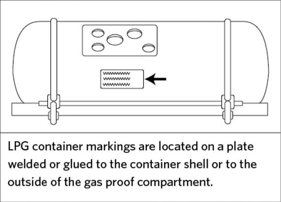
Figure 1-3-1. Container markings
Summary of legislation
Applicable legislation
- AS/NZS 1425: 2003, section 6.9.2(b).
Condition
1. The container must be stamped with the test date and the identification mark of the cylinder testing station.
2. The date stamp on a container must be within ten years of the next alternative fuels inspection.
3. A container must not be damaged by impact to the extent described in Table 1–3–1.
1-4 Container attachment
Reason for rejection
Condition
1. The security of the container attachment has been affected or weakened by:
a) rust, corrosion, abrasion or impact damage, or
b) loose nuts, worn or stretched bolts, or
c) loose bands, wear under bands, incompatible band materials, or
d) incorrect orientation of the container, or
e)visible cracks or signs of metal fatigue.
Summary of legislation
Applicable legislation
- AS/NZS1425: 2003, section 6.9.2 (e).
Condition
1.A container attachment must not have any of the following conditions such that the security of the attachment is at risk:
a) rust, corrosion, abrasion or impact damage
b) loose nuts, worn or stretched bolts
c) loose bands, wear under bands, incompatible band materials
d) incorrect orientation of the container.
1-5 Fuel system components
Reasons for rejection
Mandatory equipment
1. A component listed in Table 1-5-1 is missing.
2. An item in Table 1-5-1 is not mounted directly on the container without any intermediate pipe or fitting, except for those components associated with a remote filling arrangement or an automatic fuel shut-off device fitted to containers manufactured prior to January 1994.
Filler connection
3. The filler connection cap is:
a) missing, or
b) not held captive by a strap or similar device where it would be practicable to do so.
4. The sealing washer is missing.
5. The filler connection is not protected by the body panel or by something equivalent.
6. An automatic fuel limiting valve is fitted and a notice is not displayed at the filler connection that reads AFL FITTED.
Safety valve system
7. A safety valve:
a) is mounted with another valve between it and the container, or
b) discharges towards or into a passenger compartment, or
c) discharges directly on:
i. the container, or
ii. bystanders, or
iii. adjacent vehicles, or
d) does not discharge either:
i. into a compartment or sub-compartment, or
ii. vertically upward with a tolerance of 45° from the vertical.
Permitted equipment
8. An automatic fuel shut-off device is fitted and:
a) it is not mounted directly on the container, or
b) there is no fuel filter between it and the container.
Condition
9. A fitting is not in safe working condition (Note 1).
10. The wording on a label in Table 1-5-1 is not clearly legible.
Filler connection
11. The coupling is damaged or contains foreign matter.
12. The condition of the sealing washer is unsatisfactory.
13. The filler connection housing is not soundly attached to the vehicle.
14. The remote fill line is damaged or twisted.
Hydrostatic relief valve
15. A hydrostatic relief valve is damaged, blocked or has been tampered with.
Note 1 Definitions:
Automatic fill limiter means a provision in the filling system which automatically terminates filling when a predetermined liquid level in the container has been reached.
Automatic fuel shut-off device means a provision for automatically shutting off the fuel supply unless certain essential conditions exist.
Contents gauge means a gauge which gives a visual indication of the liquid content of the container. This may be read at the container or remotely.
Excess-flow valve means a valve normally in the open position which closes automatically when flow in a specified direction exceeds a predetermined limit.
Hydrostatic relief valve means a valve whose purpose is to relieve and prevent overpressure in any fuel service line carrying LPG liquid.
Safety valve means a valve which automatically discharges vapour into the atmosphere so as to prevent a predetermined pressure being exceeded. It is activated by the static pressure upstream of the valve.
Service valve means a manually operated shut-off valve fitted on the container which can open or shut-off the LPG supply to the engine for maintenance servicing or emergency requirements.
Note 2
Older systems may have a manual bleed valve instead of an automatic fill limiting valve.
Table 1-5-1. Mandatory and permitted LPG alternative fuel system components (Note 1)
|
Mandatory LPG alternative fuel system components |
Permitted LPG alternative fuel system components |
|---|---|
|
Filler connection Filler cap Filler non-return valve system Automatic fill limiting valve (Note 2) Service valve (fittings to NZS 5422: 1987, Part 1 must have a permanent label with the words SERVICE VALVE or similar) Excess flow valve Safety valve Contents gauge with a label adjacent to the bleed valves with the words STOP FILLING WHEN LIQUID APPEARS |
Automatic fuel shut-off device, mounted directly on the container, with a fuel filter between it and the container that is capable of removing from the fuel all particulate matter that could cause malfunction of the automatic fuel shut-off device or pressure regulator Hydrostatic relief valve Any component that forms part of the originally certified LPG alternative fuel system |
Summary of legislation
Applicable legislation
- Land Transport Rule: Vehicle Standards Compliance 2002
- Land Transport Rule: Vehicle Equipment 2004
- AS/NZS1425: 2003, section 3.3.
Mandatory equipment
1. An alternative fuel system with a fixed LPG container must be fitted with the components in column 1 of Table 1-5-1.
2. The components in Table 1-5-1 must be mounted directly on the container without any intermediate pipe or fitting, except for those components associated with a remote filling arrangement.
Filler connection
3. The filler connection must have:
a) a cap that is captive (where practicable), and
b) a sealing washer.
4. The filler connection must be recessed below the body panel or be provided with equivalent protection.
5. If an automatic fuel limiting valve is fitted, a notice must be displayed at the filler connection that reads AFL FITTED.
Safety valve system
6. A safety valve:
a) must be mounted with no valve between it and the container, and
b) must not discharge towards or into a passenger compartment, and
c) must not discharge directly on:
i. the container, or
ii. bystanders, or
iii. adjacent vehicles.
d) must release gas:
i. into a compartment or sub-compartment, or
ii. vertically upward, with a tolerance of 45° from the vertical, at a remote discharge point.
Permitted equipment
7. An LPG alternative fuel system may be fitted with the components permitted in Table 1-5-1.
8. An automatic fuel shut-off device, if fitted, must be mounted directly on the container, with a fuel filter between it and the container that is capable of removing from the fuel all particulate matter that could cause malfunction of the automatic fuel shut-off device or pressure regulator.
Condition
9. Container fittings must be in safe working condition.
Filler connection
10. The coupling must be in sound condition and free of foreign matter.
11. The sealing washer must be in satisfactory condition.
12. The filler connection housing must be soundly attached to the vehicle.
13. The remote fill line must not be damaged or twisted.
1-6 Gas proof compartment
Reasons for rejection
Mandatory equipment
1. A container is located within the body shell of a vehicle and no compartment or sub-compartment is fitted (Note 1).
2. The compartment or sub-compartment is not vented to the atmosphere.
3. The service valve is not readily accessible to authorised people or cannot be operated without the use of tools or cannot be operated fully.
4. A fixed liquid level indicator bleed valve is fitted but is not readily accessible when filling or cannot be operated without the use of tools.
5. Fittings to AS/NZS 1425: 2003: A gastight hatch is not provided with a marking that reads WARNING: KEEP CLOSED AND GASTIGHT EXCEPT WHEN THE SERVICE VALVE MUST BE OPERATED.
Condition
6. Any of the compartment structure, joints, conduit connections or pipe bulkhead seals are deteriorated, damaged, kinked or punctured so that gas may leak or gas flow through a vent could be restricted.
7. The compartment or sub-compartment is inspected and found not to be gastight (Note 2).
Note 1
Compartment means a structure which encloses the whole of the container and its fittings, whose purpose is to collect any gas leakage which might occur, so that it can be discharged to open air. A car boot is not an acceptable compartment under 1 above.
Sub-compartment means a structure attached to the container, which encloses the container fittings, and whose purpose is to collect any gas leakage which might occur, so that it can be discharged to open air.
Note 2
AS/NZS 1425: 2003, section 6.8.2 describes a standard gastight test.
Summary of legislation
Applicable legislation
- Land Transport Rule: Vehicle Standards Compliance 2002
- Land Transport Rule: Vehicle Equipment 2004
- AS/NZS1425: 2003, section 6.9.2(j)
- AS/NZS1425: 2003, section 3.17.
Mandatory equipment
1. Where a container is located within the body shell (Note 1) of a vehicle, either
a) the whole of the container and its attached components and fittings must be enclosed in a compartment that is vented to the atmosphere, or
b) the valves, fittings and pipe connections associated with or attached to the container must be enclosed in a sub-compartment attached to the container and vented to the atmosphere.
2. The service valve and, where appropriate, the fixed liquid level indicator bleed valve, must be readily accessible and operable without the use of tools.
3. Fittings to AS/NZS 1425: 2003: A gastight hatch must be provided with a marking that reads WARNING: KEEP CLOSED AND GASTIGHT EXCEPT WHEN THE SERVICE VALVE MUST BE OPERATED.
Condition
4. The compartment structure, joints, conduit connections and pipe bulkhead seals must not be deteriorated, damaged, kinked or punctured so that gas may leak or gas flow through a vent could be constricted.
5. The compartment or sub-compartment must be gastight.
1-7 Dual-fuel selector
Reasons for rejection
Mandatory equipment
1. Where LPG is not the only fuel supply, no dual-fuel selector is fitted.
2. Fittings to AS/NZS 1425: 2003: The dual-fuel selector is visible to the driver in the normal driving position and is not marked to indicate the selected fuel.
Condition
3. The dual-fuel selector is:
a) not in working condition, or
b) requires the use of tools to be operated.
4. The dual-fuel markings are illegible.
Performance
5. The fuel selector does not allow the supply of the indicated fuel.
6. The fuel selector allows the supply of more than one fuel at a time in positions where this is not intended (Note 1).
Note 1
Some systems are designed to allow petrol and LPG to flow when switching from LPG to petrol.
Summary of legislation
Applicable legislation
- Land Transport Rule: Vehicle Standards Compliance 2002
- Land Transport Rule: Vehicle Equipment 2004
- AS/NZS1425: 2003, section 6.9.2(h)
- AS/NZS1425: 2003, section 5.9.
Mandatory equipment
1. Where alternative fuels are available the vehicle must be fitted with a fuel selector to prevent the supply of more than one fuel at a time (Note 1).
2. Fittings to AS/NZS 1425: 2003: The dual-fuel selector, if visible to the driver in the normal driving position, must be marked to indicate the selected fuel.
Condition
3. The selector must be in working condition and operable by hand without the use of tools.
Performance
4. The fuel selector must allow the supply of the alternative fuels one at a time.
1-8 Location and ground clearances
Reasons for rejection
Mandatory equipment
1. An installation to NZS 5422: 1987, Part 1 does not meet all the requirements in the left-hand column of Table 1-8-1.
2. An installation to AS/NZS 1425: 2003 does not meet all the requirements in either:
a) the right-hand column of Table 1-8-1, or
b) the left-hand column of Table 1-8-1 if the requirements in the right-hand column are not practicable.
Table 1-8-1. Location and ground clearance requirements
|
Requirements from NZS 5422: 1987: Part 1 |
Requirements from AS/NZS 1425: 2003 |
|---|---|
|
1. Containers, fittings and pipework must be mounted inside the perimeter of the vehicle. 2. Container valves on externally mounted containers must be positioned no less than 200mm from the vehicle extremities. 3. A container must not be fitted: a) on the roof or above a passenger compartment b) forward of the rear of the driver’s seat in its rearmost position without specific approval c) in a position beneath the vehicle that decreases the effective ground clearance. 4. A container located between or behind the axles must be within the zone limit shown in Figure 1-8-1. |
1. The whole of a fuel container, compartment and subcompartment must lie within the ground clearance zone limits indicated by Table 1-8-2 and Figure 1-8-2 and Figure 1-8-3. 2. A container must not be mounted outside the body contour to the front or sides of the vehicle. 3. A container must not be mounted outside the body contour to the rear or top of the vehicle without specific approval. 4. A container installed inside a vehicle must not be mounted forward of the rear of the driver’s seat in its rearmost position. |
Table 1-8-2. Ground clearance zone limits (requirements from AS/NZS 1425: 2003)
|
Vehicle mass1 |
Chassis ground clearance at rear of vehicle |
Figure that shows ground clearance zone limits |
|---|---|---|
|
Less than 4500kg |
600mm or less |
Figure 1–8–2 |
| Less than 4500kg | More than 600mm | Figure 1–8–3 |
| 4500kg or more | 600mm or less | Figure 1–8–2 |
| 4500kg or more | More than 600mm | Figure 1–8–3 |
1 Unladen mass with fuel, coolant and oil containers full.
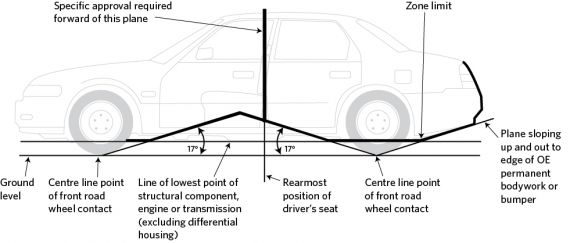
Figure 1-8-1. Zone limit for container location (requirements from NZS 5422: 1987, Part 1)
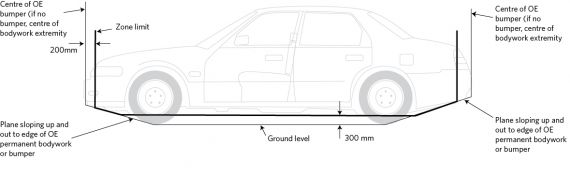
Figure 1-8-2. Ground clearance zone limits for a small vehicle (requirements from AS/NZS 1425: 2003)
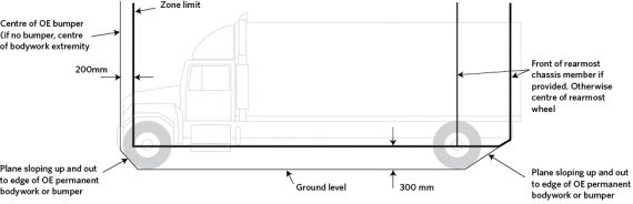
Figure 1-8-3. Ground clearance zone limits for a large vehicle (requirements from AS/NZS 1425: 2003)
Summary of legislation
Applicable legislation
- Land Transport Rule: Vehicle Standards Compliance 2002
- Land Transport Rule: Vehicle Equipment 2004
- NZS 5422: 1987, Part 1, section 2.3
- AS/NZS1425: 2003, section 6.9.2(o)
- AS/NZS1425: 2003, section 3.19.
Mandatory equipment
1. An installation to NZS 5422: 1987, Part 1 must meet the requirements in the left-hand column of Table 1-8-1.
2. An installation to AS/NZS 1425: 2003 must meet the requirements in the right-hand column or, if this is not practicable, the requirements in the left-hand column of Table 1-8-1.
1-9 Fuel service line
Reasons for rejection
Mandatory equipment
1. A fuel service line enters an enclosed driver, passenger or luggage compartment (Note 1).
2. A fuel service line in a drive shaft tunnel is within 40mm of the drive shaft under some operating conditions.
3. The underside of a fuel service line in a drive shaft tunnel is more than 15mm from the intersection of the drive shaft tunnel and the floor pan.
4. Required fuel line protection is missing.
5. A required clip or grommet is missing.
6. A pipe, hose, component or fitting subject to container pressure that is not fully protected by a radiation shield at least 15mm away is within 150mm of a hot object at a temperature above the normal water jacket temperature.
7. A pipe, hose, component or fitting subject to container pressure that is fully protected by a radiation shield at least 15mm away is within 40mm of a hot object at a temperature above the normal water jacket temperature (Figure 1-9-1).
Note 1
Fuel service line means piping, other than the fill line, used for the conveyance of LPG liquid at a pressure exceeding 450kPa.
Note 2
Corrosion damage is where the metal has been eaten away, which is evident by pitting. The outward signs of such corrosion damage are typically displayed by the lifting or bubbling of paint. In extreme cases, the area affected by the corrosion damage will fall out and leave a hole.
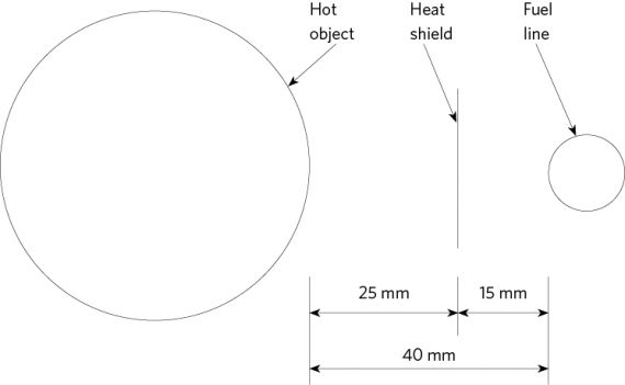
Figure 1-9-1. Minimum fuel line distance to hot object with heat shield
Summary of legislation
Applicable legislation
- Land Transport Rule: Vehicle Standards Compliance 2002
- Land Transport Rule: Vehicle Equipment 2004
- AS/NZS1425: 2003, section 4.
Mandatory equipment
1. A fuel service line must not enter an enclosed driver, passenger or luggage compartment.
2. A fuel service line in a drive shaft tunnel must not be closer than 40mm from the drive shaft under all operating conditions.
3. The underside of a fuel service line must be within 15mm of the intersection of the drive shaft tunnel and the floor pan.
4. A fuel service line below the body shell must be protected from impact or abrasion.
5. A fuel service line in a wheel arch must be
a) protected from thrown-up objects, and
b) positioned so the tyre cannot rub on the fuel line.
6. Rigid piping subject to corrosion must be protected throughout its exposed length.
7. Rigid piping must be secured to the chassis frame or body with cushioned clips not more than 600mm apart.
8. Hoses must be secured to the chassis frame or body with clips not more than 600mm apart.
9. A pipe or hose must be protected with a grommet where it passes through a body panel.
10. A pipe, hose, component or fitting subject to container pressure, and not fully protected by a radiation shield at least 15mm away, must not be within 150mm of a hot object at a temperature above the normal water jacket temperature.
11. A pipe, hose, component or fitting subject to container pressure, and fully protected by a radiation shield at lest 15mm away, must not be within 40mm of a hot object at a temperature above the normal water jacket temperature (Figure 1-9-1).
Condition
12. An alternative fuel system in working order must be in a safe working condition.
1-10 System gastightness
Reasons for rejection
Condition and performance
1. With LPG in the container and fuel lines full of LPG liquid, and all pipe connections tested for leaks, a leak is indicated.
2. With LPG in the container and fuel lines full of LPG liquid, and all valves tested for leaks in both open and closed positions, a leak is indicated.
Note 1
Guidance on acceptable leak detection methods are given in AS/NZS 1425: 2003 appendix C.
Summary of legislation
Applicable legislation
- Land Transport Rule: Vehicle Standards Compliance 2002
- Land Transport Rule: Vehicle Equipment 2004
- AS/NZS1425: 2003, section 6.9.2(a).
Condition and performance
1. Pipe and component connections must be gastight.
2. All manual valves must be gas tight in both open and closed positions.