Correct as at 26th April 2024. It may be superseded at any time.
Extract taken from: Vehicle Inspection Portal > VIRMs > Heavy vehicle specialist certification > Technical bulletins > Modifications to truck cabs
20 Modifications to truck cabs
This technical bulletin provides guidance to heavy vehicle specialist certifiers regarding modifications to trucks’ cabs to ensure compliance with land transport legislation. It’s also expected to serve as a reference for modifiers and importers of modified trucks.
1. Background
It is common practice to modify the cab of a truck to produce a crawl-through or walk-through between the truck’s cab and a custom-made body. Typical examples are motor caravans, truck buses, horse trucks, and other similar special purpose vehicles.
The three critical elements of crashworthiness are the structural integrity of the vehicle (cab), residual space for occupants, and restraint systems. A truck’s cab provides fundamental protection to occupants in the event of an accident.
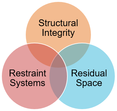
Figure 20-1-1. Three critical elements of crash worthiness
Research and testing have found that even relatively minor modifications to truck cabs can significantly reduce their structural integrity. In the event of a crash, this reduction in structural integrity undermines the survival space for occupants and performance of occupant restraint systems.
In addition to frontal impact protection, modern truck cabs also have inherent structural integrity providing occupant protection from roof loads and side loads (a load applied approximately perpendicular to the longitudinal axis of the vehicle), as to be expected in a truck rollover.
This guidance is primarily aimed at bespoke modifications, not mass-produced variants. Physical testing would result in a damaged cab so is not an option and full engineering analysis of a single modified truck cab can not be done within the financial and time budget restrictions of most conversions.
To that end, common modifications have been reviewed, tested, and recommendations made to produce these general guidelines as a reference for bespoke modifications.
Notwithstanding, the methodology covered here could be applied to series-produced vehicles, where the initial cost of full engineering analysis could be amortised over the series.
2. Legal requirements
The Land Transport Rule: Vehicle Standards Compliance 2002 requires that a modification to a vehicle must result in that vehicle being safe to be operated, designed and constructed using components and materials that are fit for their purpose, and within safe tolerance of its state when manufactured or last certified as a modified vehicle.
Safe tolerance is a defined term and means the tolerance within which the safe performance of the vehicle, its structure, systems, components or equipment is not compromised, having regard to any manufacturer’s operating limits.
The principal that vehicles remain within safe tolerance of their state of manufacture is known as continued compliance.
After modification, the demonstration of continued compliance with only one aspect (such as roof loads, for example) does not validate the inherent, as-manufactured performance of the cab under other loads, such as side loads, for example.
In all instances a vehicle modifier should involve a heavy vehicle specialist certifier in a modification project from the beginning of the project. Failure to do so may result in added costs and delays resulting from the certifier’s obligations.
In summary, there are two primary responsibilities of a specialist certifier in respect of cab cut-outs;
- Inspection of the modifications to ensure they were designed and constructed using components and materials that are fit for their purpose.
- It is highly recommended that the specialist certifier be provided access to the in-progress vehicle, or other verifiable means of documentation. Otherwise, the trim may be damaged during the course of this mandatory inspection.
- Demonstration that, after modifications, the safety of the occupants has not been compromised, having regard to the level of safety the occupants had in the as-manufactured, unmodified cab.
Note: manufacturers’ body builder’s guides commonly feature sections describing where cuts should be made when work is required. While these guides are useful for describing where to (and more importantly, where not to) cut, unless specific guidance for how to reinstate the integrity is described, they must not be considered a replacement for these guidelines. Instead, they should be read in conjunction with these guidelines.
3. Testing overview
To understand how modified cabs performed compared to OEM, the Agency engaged Sandbox Consulting to conduct testing on typical modifications to truck cabs of different GVM ranges. The cabs were tested with the following modifications:
- Modifications to the rear wall only
- Modifications to the rear wall and roof where the structural rings of the cab have been removed
The comparative performance of the cabs demonstrated the relative stiffness of the cabs under loading and the limits at which plastic hinging occurs. After plastic hinging, further loading would continue to deform the cabs, without significant resistance. In the final test of each cab, they were loaded until the cab structure impinged into the approximate residual space of the occupants.
3-1 Modifications to the rear wall only
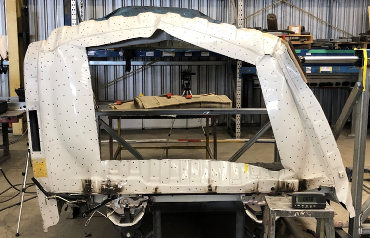
Figure 20-1-2. Modifications to the rear wall only, Japanese (after testing)
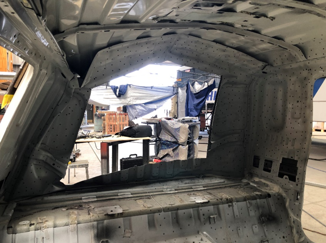
Figure 20-1-3. Modifications to the rear wall only, Japanese (internal, after testing)
3-2 Modifications to the rear wall and roof where the structural rings of the cab have been removed
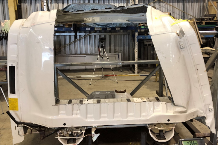
Figure 20-1-4. Modification to the rear wall and roof, Japanese (during testing)
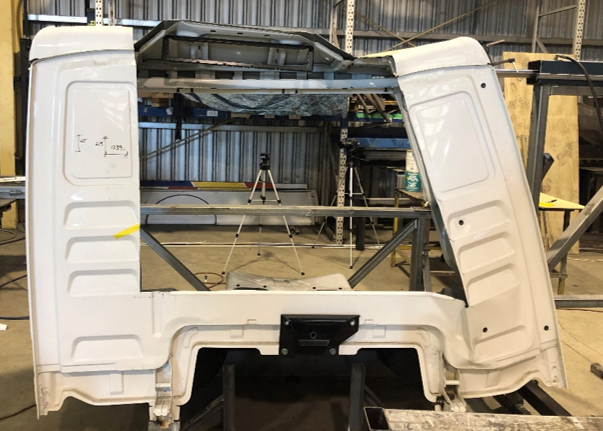
Figure 20-1-5. Modification to the rear wall and roof, European (during testing)
4. Test results
4-1 Strain energy
The results are reproduced using a load-deflection curve (refer to Hooke’s Law). When force is applied to a structure it deforms and stores potential energy. The strain energy is the potential energy stored due to the deflection. Up to the elastic limit, the strain in the structure is also elastic and will be recovered when the load is removed (i.e. the material returns to its original length). However, if the material is loaded beyond the elastic limit, a permanent deformation in the material will take place, this is referred to as plastic strain. The plastic strain of the structure is necessary to achieve energy absorption.
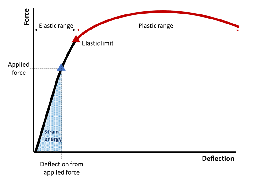
Figure 20-1-6. Load-deflection curve
The area under the curve can be related to the strain energy (work done) and the slope of the curve to the structure’s stiffness. The stiffer a structure is, the steeper the force-deflection curve.
4-2 Cab comparison elastic range
Several tests were performed on each cab with the different modifications in the elastic range. The final test loaded the cab structures past the elastic limit and into the plastic range.
The results of all the tests in the elastic range are shown in Figure 20-1-11, including the curve gradients and linear regression values. Linear regression is a statistical method that allows one to summarise and study relationships between two continuous (quantitative) variables. The results show a strong linear (proportional) relationship between force and displacement in the linear elastic range (as expected). The close clustering of data points between tests shows repeatability of the experimental setup. The difference in maximum load capacity between the Japanese and European cabs is primarily due to the size of truck to which they were fitted (i.e. different GVMs).
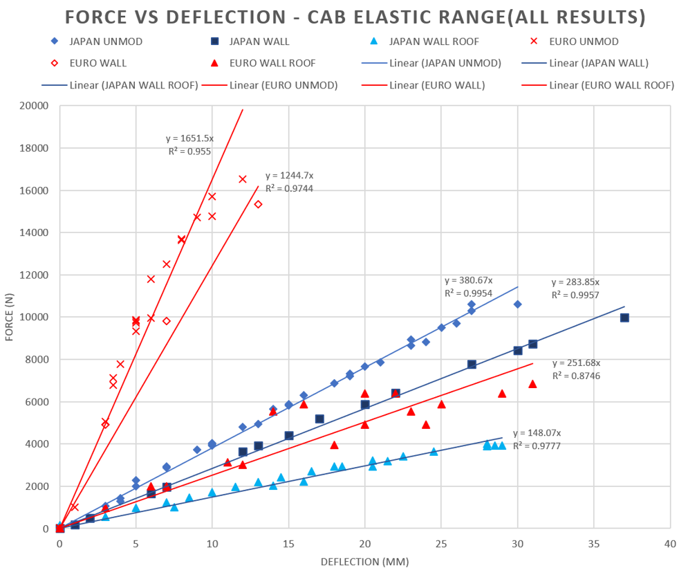
Figure 20-1-7. Force deflection curve elastic range
4-3 Summary of results – elastic range
The results show the cab elastic stiffness is significantly reduced by the modification of the cab structure.
For the Japanese cab, the modification to the rear wall resulted in a stiffness reduction of 26%, while the combined modification to the rear wall and roof resulted in a 61% reduction.
For the European cab, the modification to the rear wall resulted in a stiffness reduction of 25%, while the combined modification to the rear wall and roof resulted in an 85% reduction.
The large difference between the Japanese cab and European cab after the combined modification to the rear wall and roof is due to the design philosophies used by the manufactures, particularly;
- The style of reinforcement used in the rear wall of the cabs, and
- The height differences between the cab (the European cab was higher), and
- Subfloor reinforcement in the Japanese cab.
Note: the cab test results are not intended to be a statement about the manufacturers or country of origin. The tests were carried out to determine the effect of modification to truck cabs.

Figure 20-1-8. Force vs deflection Japanese cab - plastic deformation test
4-4 Summary of results - plastic range
In the plastic loading phase of the testing, several more complicated behaviours were observed, these included the failure of welds, tearing of material, and crumpling of the cab side wall (localised buckling).
Due to the limited availability of identical cabs for testing, the unmodified cab was not loaded to the same level as the one modified with the rear wall only or the one with the rear wall and roof modifications. The test was stopped when significant plastic deformation had occurred.
5. Reinforcement types
When considering how to return the level of occupant protection to within safe tolerance of the cab’s state of manufacture, there are two main options; integrated reinforcement and an independent protective structure.
5-1 Integrated reinforcement
Integrated reinforcement is where the truck cabin and reinforcing structure are directly connected using permanent fixings, as illustrated below.
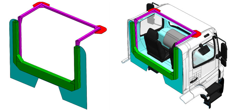
Figure 20-1-9. Example of integrated reinforcement for a rear wall and roof cutout
5-2. Independent protective structure
An independent protective structure is one where the truck’s cab is independent of the protective structure (not permanently attached). This configuration is typically found in truck bus conversions where the structural reinforcements in the body necessary for meeting the PSV Rule provide protection for the occupants of the cab.
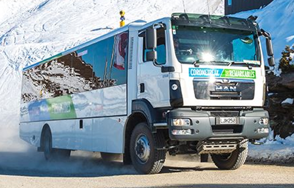
Figure 20-1-10. Typical New Zealand truck bus
(image courtesy NZ Ski)
In situations where it’s appropriate or necessary to make an independent protective structure, it must be shown that:
- The deflection of the body’s protective structure provides adequate protection to the truck cab, and
- The structure must be adjacent to the area of modification (rear wall cut out, with protective frame directly behind), and
- The modification only reduces the strength or stiffness of the cab by less than 25% (e.g. modifications such as enlarging the rear window area but not cutting into the main ring frames of the cab structure), and
- The modified cab structure together with the protection provided by the independent protective structure provide protection for occupants of the cab within safe tolerance of the cab alone when new, and
- The body attachment is fit for purpose.
6. Engineering analysis
In all cases, the engineer must ensure the seatbelt anchorages, seat anchorages, safety systems, and frontal impact performance of the cab is not undermined.
6-1 Modification ‘traffic light’
The engineering analysis required depends on the extent of the modifications. The engineering solutions increase dramatically in complexity from left (‘green’) to right (‘red’), below. Only those certifiers with demonstrated expertise in nonlinear finite element analysis should engage in certifications toward the amber and red side.
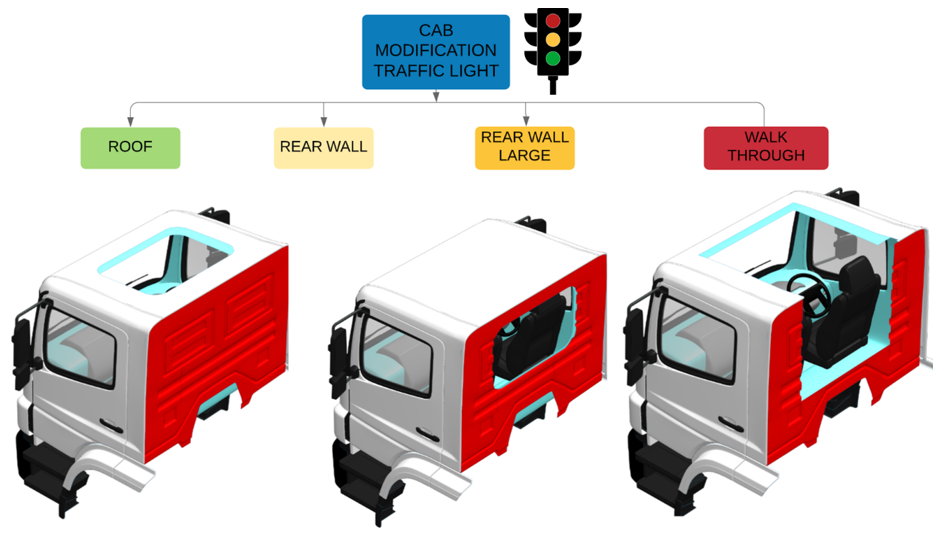
Figure 20-1-11. Cab modification 'traffic light'
Amber and red indicate higher levels of complexity of engineering analysis.
6-2 Cab modification design methodologies
A modern truck cab is designed to absorb and dissipate the ensuing energy of an impact around the body of the cab. Particular attention is required to balance the thickness and stiffness of a reinforcing frame and the parts of the cab to which it is attached. As an energy-absorbing system, overbuilding or over-reinforcing the cab may lead to an unsafe condition.
As noted previously, to demonstrate that a modified cab is returned to within safe tolerance of its original condition, the certifier must show the truck cab performs in a similar way after modification as it did when manufactured to any reasonable load case, including side loads.
6-3 Using UN/ECE Regulation Number 29 (‘R29’) as a benchmark
R29 sets the requirements for occupant safety in the United Nation Economic Commission for Europe (UN/ECE) countries. The standard has become ubiquitous in the truck manufacturing industry both in and outside of Europe. Most truck cabins imported into New Zealand now comply with R29.
To pass R29 a cab may not undergo deformation dangerous to the occupants (penetration into the survival space) when subject to the required test loads. The R29 test uses a pass/fail criterion of survival space large enough for an occupant, so it is the extent of local deformation that is crucial because if any one part of the structure intrudes into this space, the test is failed.
During tests, illustrated below, the components by which the cab is secured to the chassis may be distorted or broken, provided that the cab remains attached to the chassis frame. None of the doors shall open during tests, but the doors shall not be required to open after testing.
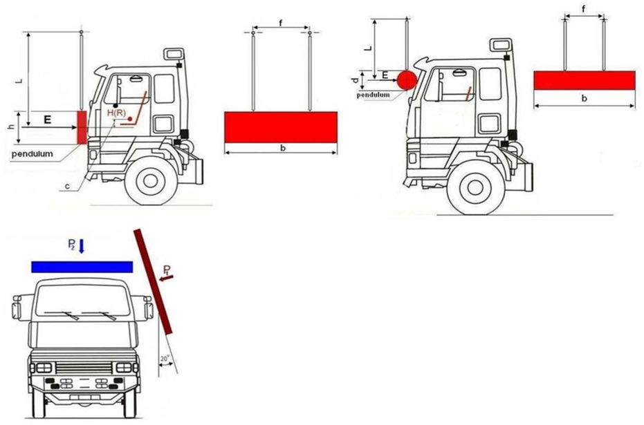
Figure 20-1-12. Impactors from UN/ECE Reg. No. 29 Rev 2.
For industry consistency, either a dynamic load with the R29 impactor, or a quasi-static load using the R29 impactor angles is recommended to use for engineering analysis.
In determining the inherent strength of cabs to side loads, the R29.03 series of amendments are recommended to be used as a benchmark (even if the cab complied with a previous version of the standard which did not include a side-loading test, or another standard).
For the avoidance of doubt, for the comparative analysis, it’s not expected that the modified cab will be capable of demonstrating full compliance with the requirements of R29.03. Instead, it’s a useful benchmark to compare the relative performance between the unmodified and the modified cab to ensure the modified cab is within safe tolerance of its state of manufacture.
6-4 An iterative approach to solving the problem
Finite element analysis (FEA) should be used to justify the modification to truck cabs. A satisfactory result is reached when it can be shown that the force-deflection curves are within safe tolerance comparing the modified to the unmodified cab. The finite element analysis should be done following best practice and include a mesh sensitivity study. Any geometry simplifications (excluding omission of minor features) of the structure should be noted and justified. The flowchart, below, illustrates an iterative approach that can be employed.
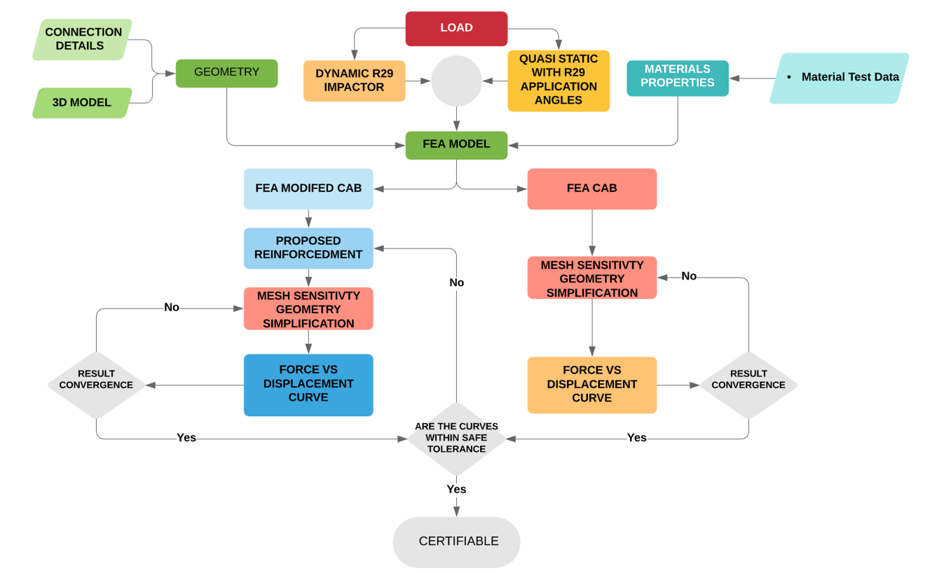
Figure 20-1-13. Process flowchart
There are no appropriate methods available for hand calculation when an integrated approach is taken, with the exception of modifications to PSVs which must comply with the PSV rule.
The following recommendations are made for suitable FEA software:
- The computer software and model must be capable of describing the real physical behaviour of the system under load, ie non-linear plastic collapse. Hand calculations won’t work.
- The model must be constructed, and assumptions prescribed, in such a way that the calculations give conservative results. The engineer should obtain enough material data to support material assumptions used in calculations or models for the areas where the reinforcement and cab are connected, and which are part of the computer model.
- Shell elements are the most suitable method to represent the structural elements used to construct a cab.
- Only materials of known properties may be used for the construction.
- Non-metallic materials may be used; however, the aggregate strength of the system must be demonstrated using physical testing.
- A mesh sensitivity study should be used to demonstrate convergence. Mesh resolution should be appropriate for areas in large deformation areas and around stress concentrations.
- Connections should be modelled appropriately (e.g. spot-welds, bolts and rivets, etc.).
- Glues may be used but physical testing is required to demonstrate aggregate strength.
- The calculations must include an allowance for deterioration during the expected life of the vehicle where appropriate, having regard to the material of the structure, the specific manufacturing technology, and conditions under which the vehicle is likely to be operated.
7. Welding Standards and Material Data
7-1 Cab body welded connections and material
The material properties for cab panels and their weldability are often difficult to obtain from the manufacturer. Different trucks vary in construction methodology and material choice.
The materials used to construct truck cabs range from mild steel (180 MPa), high strength steel (HSS) to ultra-high-strength steel (UHSS - 1500 MPa). A single cab is often made up of a mixture of different materials.
The use of advanced high-strength steels (AHSS), which are thinner, lighter, stronger and have superior performance absorbing impact energy, is increasing. The use of these materials in truck cabs raises concerns about identification, characteristics, where they are used in the cab and to what extent they can be repaired or modified. If not identified by the manufacturer, it is recommended that a certifier conclusively identifies the material.
7-2 Welding to the cab
Generally, the welding process and material specification of the cab panels falls outside the scope of NZS 1554 and the AS/NZS 2980 and AS/NZS ISO 9606.1 welder qualification.
Due to this, the certifier should use welding processes and consumables specified by the vehicle manufacturer for repair or replacement of body panels where available (panel beaters guide or specifications). In some cases, general provisions are provided; however, care must be taken to ensure these apply to the specific panels affected or part of the welded connection.
Plug weld size and spacing and seam weld length may be referenced to determine the connection of additional reinforcements.
If the material and welding information is not available, the certifier may:
- Obtain material test certificates, from suitability accredited test laboratory, for the parts of the vehicle body used in the welded connections and computer models. The material test should include material properties and information relating to weldability.
The test data from a single cab of the same make and series may be used to support the certification of multiple vehicles. However, the certifier must have records to show the cabs are identical and are common to all models in the same GVM range.
Welding should be performed by welders qualified by a recognised industry qualification used in light vehicle repair such as I-Car.
7-3 Welding of reinforcements
In all cases the certifying engineer must:
- Identify the parent metal, and
- Choose the appropriate standards (only current versions of the standards may be used) for design and fabrication, and
- Ensure compliance with those standards of all parties encompassed in the certification, and
- Provide evidence of sufficient strength of the welded component.
The following welding standards may be applicable for the welding/fabrication of the reinforcement structure:
- AS/NZS 1554.1, Structural Steel Welding, Part 1, Welding of Steel Structures (minimum yield strength not exceeding 500 MPa)
- AS/NZS 1554.4, Part 4, Welding of High Strength Quenched and Tempered Steels (minimum yield strength not exceeding 1000 MPa)
- AS/NZS 1554.5, Part 5, Welding of Steel Structures Subject to High Levels of Fatigue (minimum yield strength not exceeding 450 MPa)
- AS/NZS 1554.6, Part 6, Welding of Stainless Steel.
- AS/NZS 1665 Welding of Aluminium Structures
- AS/NZS 1554.7 Structural steel welding of sheet steel structures
7-4 Boron alloyed
The UHSS alloyed with boron is at the higher end of the advanced metals used in truck cab construction.
Parts made from UHSS alloyed with boron should not be straightened or reformed. The steel panels are formed at extremely high temperatures and are prone to work hardening and cracking if damaged or deformed.
Boron UHSS is weldable, and either the GMA (MIG) welding process or squeeze-type resistance spot welding can be used. To maintain the high strength characteristics of the steel, it is important to limit the heat-effected zone.
Information relating to the different issues may be found from industry organisations such as I-Car.
7-5 Material data
The engineer should obtain enough material data to support material assumptions used in calculations or models for the areas where the reinforcement and cab are connected, and which are part of the computer model.
Where the manufacturer specifies a welding process for the area involved in the modification, the material test data may be limited to the tensile test report.
7-6 Alternative materials
Several truck manufacturers use alternative materials for the construction of cab components such as fibre reinforced composites (FCR) or aluminium.
If these components form part of the strength of the cab the engineer must demonstrate any modifications return them to within safe tolerance of their original manufacture, considering the aggregate strength of the materials and connections between components.
7-7 Rivets and bolted connection
The use of rivets and bolts is allowable provided the certifier can show the fasteners have enough bearing area and strength and do not suffer from tear-out. Only structural rated rivets and high tensile bolts should be used. It is recommended that an adhesive system is used in conjunction with bolted and rivet type connections.
7-8 Adhesive joints
The use of adhesives in the connection of reinforcement may be beneficial if not prudent. The use of adhesive in joints provides the following advantages:
- Helps to reduce the stress concentration found in bolded, riveted and welded joints.
- Eliminates sudden changes in stress.
- Shock and impact characteristics of the joint are improved.
- Allows joining of dissimilar materials
- Adhesives can contour and form to complex surfaces.
The engineer, depending on an adhesive joint, must be able to demonstrate:
- A prequalified adhesive system was used, and all requirements in product data sheets were met in the application and use of the product – substrate preparation, adhesive thickness, the temperature and humidity.
- Calculations for the adhesive joints include the expected stress in service and as an occupant protection structure – specifically the orientation, magnitude and frequency of applied loads.
- A test sample is used to validate the connection.
- A suitable factor of safety is used in the design of the adhesive joint considering:
- Adhesive properties
- Environmental conditions
- Fatigue
- Appropriate allowance for deterioration during the expected life of the vehicle.
An adhesive system should be used in conjunction with mechanical rivets or spot welding.
8. Additional Considerations
8-1 Steel grain direction
Folded sheet steel subjected to dynamic high-stress loads can tear along folds. Careful attention must be paid to grain or rolling direction when bending high-strength metals, especially when resulting in small inside bend radii. In steel, the ductility in the direction of rolling is almost twice that at right angles to the direction of rolling. When bending high-strength materials, the part should be orientated so that it can be bent against the grain. Bending with the grain may result in cracking or even breaking in the deformation area.
This attention to grain direction should be noted on engineering drawings.
The direction refers to grain fibre following the direction of rolling and parallel to edges of strip or sheets. To bend across the grain is to bend at right angles to the direction of rolling; to bend with the grain is to bend parallel to the direction of rolling.
8-2 Body attachments
In cases where the truck cab to chassis attachments are modified or replaced with rigid attachments, the attachments should be suitable to maintain the cab structure on the vehicle under the specified loads in the design section of this guideline; this is part of the cab’s compliance.
Additional induced loads on the chassis and cab structure due to the rigid mounting must be considered and justified.
8-3 Restraints and airbags
The engineer must demonstrate that the level of modification has not undermined the function of the seatbelts, seatbelt anchorages or airbags.
8-4 Exhaust systems
The certifier must ensure that the vehicle exhaust system gases cannot enter the passenger compartment.
8-5 Corrosion protection
Adequate coating and corrosive protection of the cab after modification must be applied to reduce the likelihood of deterioration of the cab structure.
8-6 Durability considerations
Consideration must be given to the modification’s impact on the durability of the cab and associated components.
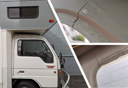
Figure 20-1-14. Cracks developing due to insufficient reinforcement after cab modifications
8-7 HV engineer certifiers and HV manufacturer certifiers
Certifying engineers issuing a Statement of Design Compliance (SoDC) for cab/body modification or repairs which affect the occupant protection have total accountability for fulfilling all statutory and legal obligations concerning such activities.
A SoDC is a formal declaration that the certifying engineer has fulfilled all such requirements and is accountable for the integrity of the manufacture, repair or modification.
Refer to section 11 Local manufacturing for requirements of HV manufacturing certifiers.
Page added 11 August 2020 (see amendment details)