Correct as at 20th April 2024. It may be superseded at any time.
Extract taken from: Vehicle Inspection Portal > VIRMs > Heavy vehicle specialist certification > Technical bulletins
Technical bulletins
1 Heavy vehicle repair thresholds
| This technical bulletin replaces and incorporates Memo 30 and 63. |
Except as otherwise noted, any heavy vehicle that has been structurally damaged and requires repair also requires HV specialist certification.
Any heavy vehicle requiring repairs (including one that has been assessed by an insurer as requiring repairs) after an accident requires heavy vehicle specialist certification if repairs involve:
- structure (chassis), or
- brakes, or
- suspension, or
- steering, or
- any certifiable component (eg towing connection, load anchorage, etc.).
Note 1
The cab is a structural member and is included in this requirement. Heavy vehicle specialist certification is required where the cab structure has been damaged or where any part of the frontal impact protection system, seat mounting, seatbelt anchorage, cab mounts and latches and any other critical load path may have been compromised.
Note 2
Where the damage includes systems or components not normally certified by the HVSC, that certifier should use the skills of others but the HVSC takes ultimate responsibility for the repairs.
Note 3
Where critical suspension components such as axles, hubs, stubs, etc. are reused, they become part of the certification and the certifier must be satisfied that they have not been subject to forces which would preclude such reuse.
Water or fire damage
Any heavy vehicle that has been identified as water or fire damaged (whether written off by the insurer or not) requires the HVSC to carry out a comprehensive inspection of all areas and systems to ensure no structural damage has occurred from corrosion or heat and all critical safety systems (eg brakes, air bags, seatbelt pre-tensioners, etc.) operate safely.
Note 4
Table 9-1-1 in the VIRM: Light vehicle repair certification is a useful guide for acceptable repair of water-damaged vehicles.
Note 5
All repairs on heavy vehicle structures and certifiable components require the same levels of certification as there is not a different threshold of damage for in-service or ‘written off.
Repairs that do not require heavy vehicle specialist certification
The following repairs to heavy vehicles do not require HV specialist inspection and certification, ie an LT400.
- Replacement of bolted components, except for components that specifically require specialist inspection and certification (eg log bolster attachments, drawbars and drawbeams, etc.).
- Repairs to the first failures of chassis cross-members that are not one of the following:
- the first or last cross-member of the chassis;
- cross-members that are fitted within 500mm from engine or transmission mounts or suspension supports (e.g. spring hanger);
- cross-members that are fitted or support a:
- driveshaft centre bearing, or
- ball-race turntable, or
- tow coupling, or
- fifth-wheel, or
- king pin, or
- bolster attachment, or
- hoist, hydraulic cylinder of a tipping body, or any other devices that may place a concentrated load on the chassis.
- Repairs to coaming rails that do not support certified load anchorage points, including stock crate J-hooks.
- Tow-eyes fitted to a vehicle for recovery purposes.
- Repairs to a component of a freight or bus monocoque body (ie not a truck’s driver/passenger cab) if the component is not part of the structural framework. (eg unstressed body panels)
Note 6
The vehicle inspector may reject the component during the CoF inspection if the welding that has been carried out as part of the repair is of poor quality, established by means of visual inspection.
Page amended 9 April 2018 (see amendment details)
2 Isuzu CXH450 chassis repairs and expectation for chassis repairs and certification
| This technical bulletin replaces memo 37. |
Isuzu CXH450 chassis failures
The premature failures of Isuzu CXH450 chassis rails have been analysed and the findings (with recommended permitted stress levels) have been summarised in two reports, prepared for Isuzu NZ by Transport Engineering Research New Zealand Ltd. (TERNZ).
The Transport Agency has been advised by Isuzu NZ that in their opinion a chassis that has been repaired and reinforced so that the stress levels are not exceeding those recommended in the two TERNZ reports, the chassis would have an acceptable service life.
Steps to be taken by HVSCs for Isuzu CXH450 chassis failures
1. Before starting to design the repair and reinforcement specification, the HVSC must obtain copies of both reports by TERNZ through Isuzu NZ.
2. The grade of steel of the chassis rails must be obtained in writing from Isuzu NZ (unless the HVSC has already received confirmed data of the chassis rail material).
3. The HVSC may need to check the Body Builders’ Manual issued by Isuzu, covering CXH450 type vehicles. Note: The two TERNZ reports, the Body Builders’ Manual and the information on the chassis rail material can be obtained from the Isuzu Product Engineer (phone +64 9 978 3624).
4. When the chassis repair and reinforcement is designed, the recommended maximum stress levels (included in the TRNZ reports) must be taken into account.
Expectation when a chassis repair is certified
1. If a chassis has been damaged due to a crash or the incorrect use of the equipment (equipment abuse), the repair must reinstate the chassis within safe tolerance of its state when manufactured (or last certified subsequent to its modification). A correct repair would not significantly affect the longevity of the chassis.
2. If a premature chassis failure occurs due to fatigue, it may indicate that the chassis rating of the vehicle might be inappropriate or the vehicle might be inappropriate for the type of service it is used in. In such a case, a repair that reinstates the vehicle within safe tolerance of its condition when manufactured is not sufficient; therefore the chassis must be repaired and reinforced.
3. Transport law is silent on the issue of longevity of a vehicle or its equipment or component, and there is no specific requirement for the minimum distance or time during which a vehicle or its equipment or component must not fail. However, it is expected that if the chassis of a vehicle is repaired and reinforced correctly, it will not fail in service significantly earlier than vehicles of other makes and models, which have similar payload capacities, intended for similar usage, and operated in a similar manner and conditions.
Page amended 9 April 2018 (see amendment details)
3 Heavy vehicle chassis ratings: modification thresholds to allow a heavy vehicle’s GVM to be altered (and its chassis rating to be changed)
| This technical bulletin replaces the 57 series of memos and memo 75. |
A vehicle’s GVM is the maximum safe operating mass for a vehicle, which is derived from the design, capabilities, and capacities of the vehicle’s construction, systems, and components.
Chassis ratings determined by HVSCs
Chassis ratings can only be determined by those HVSCs holding the HVEC (chassis) category. Ratings can be applied only to New Zealand built or modified class TD and TC trailers, class NB and NC goods vehicles, and MD3 and MD4 omnibuses, as allowed for by 8.6(1) and 8.6(2) of Land Transport Rule: Heavy Vehicles 2004.
A HVSC must not set a GVM that is higher or significantly lower than the vehicle’s lowest rated component or system. Where a vehicle has an axle removed to reduce the GVM, any reduction in GVM must be reasonable.
For example, if a three-axle trailer with a GVM of 24 tonnes has one axle removed, then it is unlikely that a HVSC could justify a reduction in the GVM of more than 10 tonnes.
Note 1
If an HVSC wishes to make a change to a GVM of this magnitude then the justification should be discussed with the Transport Agency's Vehicles team (email vehicles@nzta.govt.nz) before work is carried out.
Trailer manufacturers in series production
Where a trailer manufacturer is making a series of trailers to the same design, an HMCD (local manufacturing certifier) can sign off the chassis rating against a Statement of Design Compliance (SoDC) provided by an HVEC.
It is up to the HVEC to define the range of the SoDC, whether by a range of VIN numbers, a model number with an expiry date or other suitable system.
Chassis ratings currently covered by a type approval in the ICRAT screen of LANDATA remain valid for future ratings as long as the design of the model is unchanged and the vehicle is presented with a LT400 completed by an HVCD or HMCD confirming that the vehicle complies in all ways with the model type approved.
Modifications requiring additional category of heavy vehicle specialist certification
All modifications that fall outside the thresholds for certifier responsibility require an additional category of HVSC. If the vehicle changes class as a result of the modification brake certification is still required.
Gross combined mass (GCM) and maximum towed mass (MTM)
Changes to the GCM are likely to require changes to the driveline and/or chassis – which will also require a new chassis rating. However, these can only be determined by the manufacturer.
An HVSC may not alter the GCM of a heavy vehicle where the GVM has been reduced. This must be brought to the attention of the Transport Agency with supporting information from the HVSC and the OE manufacturer to ensure that the existing GCM remains appropriate or is changed to reflect the modifications made.
Changes to the MTM (within the towing vehicle’s limits) are a function of the drawbeam or towbar certified to the heavy vehicle.
Modifications requiring new or re-validated chassis ratings
1. General thresholds of modifications
If these general thresholds are not met then there is no reason or justification to change the GVM of the vehicle:
- addition of an axle and suspension system or removal of an axle and suspension system
- relocation (>50mm) of an axle and suspension system
- the replacement of an axle or suspension system with a different type of axle or suspension system or modification of its chassis.
2. Removing an axle
Modifications such as removing an axle require that the HVSC carrying out the certification must consult a brake certifier (HVEK) to either:
- modify and re-certify the brakes, or
- provide certification that the brakes do not require further modification.
Note 2
The modifications to the chassis cannot be certified until the brake certification has been completed. The lead certifier (generally the HVEC) on the project cannot delegate the responsibility to the vehicle owner or the testing station.
Note 3
Where the vehicle has an electronic braking system or an integral stability control system the vehicle manufacturer must provide approval, in writing, for the modifications.
3. Modification to the track width
The following considerations must be taken into account for track width modifications:
- Approval from the axle manufacturer to increase the track and the axle component loadings at the original axle rating must be obtained or a detailed bearing load and axle bending moment calculation must be carried out to ensure loadings of the new configuration at the revised axle rating do not exceed the original installation.
- If such modification to the axle reduces the axle rating so that it is no longer sufficient to support the existing GVM then the GVM may be revised provided such a revision does not mean the GVM is greater than the sum of the axle ratings, but:
- the suspension must be modified to reflect the altered loadings while ensuring the load sharing requirements in the Land Transport Rule: Vehicle Dimensions and Mass Rule 2016 are maintained. This will require certification
- the brake force distribution must be altered to reflect the altered load sharing on the axles or tyre adhesion if this falls outside the manufacturer’s limits. Such a modification will require HVEK certification.
- Any change to the rear axis due to the new dual / single configuration may alter the rear overhang and place it outside the legal requirements in the Land Transport Rule: Vehicle Dimensions and Mass Rule 2016.
- If the rear axle changes, then bending stresses in the chassis must be calculated and, if there are increased stresses due to the increased rear overhang, suitable mitigation must be undertaken and certified.
- The vehicle must be plated for the variance in load share of the rear axle group.
- Such modifications will affect the vehicle’s SRT which must be confirmed as being at least 0.35g for a prime mover or certified as at least 0.35g for a trailer.
Note 4
This is not an exhaustive list of the requirements that need to be taken into account when contemplating this type of modification but shows the level of justification required for any re-rating.
4. Modifications to wheel and tyre configuration
When down-rating a vehicle’s GVM by removing wheels from a dual axle set and replacing with single or large single wheels and tyres the following must be considered and covered in the job file:
- Spacers must be used to achieve correct wheel spacing on the hub. Wheels without tyres are not acceptable.
- Any axle rating reduction arising from changes to bearing loads must be fully calculated and accurately reflect the calculated results.
- Where wheel offset changes are made to achieve required loadings and new wheel centres are welded in then material specifications must be identified by a metallurgist and appropriate welding procedures to AS/NZS 1554 (or other applicable, approved standards) must be used along with the applicable inspection and NDT processes.
- Welding must be carried out by an appropriately qualified welder.
- Suspension alterations must be considered, as appropriate to the new axle ratings, to address and mitigate any drivability issues.
- Load sharing requirements must be considered.
5. Removing a wheel and tyre from a dual tyre set
When a vehicle is modified by removing an inner tyre of a dual tyre set, that wheel and tyre assembly should be removed. It is not acceptable for the redundant wheel minus tyre to be left in place acting as a spacer or for any other reason. This modification also requires that the engineer doing the modification ensure that the requirement for brake certification is addressed.
Note 5
These modifications cannot not be certified until the brake certification has been completed. The lead certifier on the project cannot delegate the responsibility to the vehicle owner or the testing station.
6. Modifications around certain thresholds
To de-rate a vehicle around any of the specific thresholds listed below, the vehicle must be significantly modified, as described in the Rule. However, where the manufacturer builds the vehicle in more than one weight bracket, to de-rate the chassis and reduce the GVM, the vehicle must be modified to exactly match the vehicle sold by that manufacturer in that weight class:
- from a GVM greater than 3.5 tonne to a GVM below 3.5 tonne, or
- from a GVM greater than 4.5 tonne to a GVM below 4.5 tonne, or
- from a GVM greater than 6 tonne to a GVM below 6 tonne.
Example
The following modifications must be made, as required: Suspension, axles, driveline and brakes must exactly match the vehicle in the target weight bracket even if these modifications mean that brake recertification (to Schedule 5, section 6 of the Land Transport Rule:Heavy vehicle Brakes 2006) is required.
Note 6
In the above example, the manufacturer's certification cannot be used if the two certifications are different. The vehicle must be recertified by an HVEK.
7. Different GVMs of the same base vehicle
If a manufacturer offers vehicles identical in every way (except for badges, labels, etc) but having different GVMs, individual vehicles cannot be swapped between weight classes by swapping the badges, labels, etc. or assuming they are the same vehicle.
In these cases, the chassis rating/GVM which may only be changed by significant modification.
Modifications that do not justify new chassis ratings
1. Removal of a spring leaf or resetting of a spring set
The removal of a spring leaf or the resetting of a spring set does not constitute 'a different type of suspension' and cannot be solely used to justify the down rating of a manufacturer’s chassis rating.
Note: In the situation that the ride height of a vehicle, such as an ambulance, has been reduced for operational reasons, by the re-arching of the leaf spring and this results in a limitation of the available suspension travel, effectively reducing the available axle rating and thus the GVM, this reduction may be acceptable but in each case must be approved by the Transport Agency (email vehicles@nzta.govt.nz) before the modifications are carried out.
2. Minor wheelbase changes
A minor wheelbase change (eg 50mm) would require HVSC certification due the additional holes in the chassis to mount the relocated suspension, but would have no substantive effect on the chassis rating and cannot be used as a justification to reduce or increase the GVM.
These modifications cannot be certified until the brake certification has been completed. The lead certifier on the project cannot delegate the responsibility to the vehicle owner or the testing station.
3. Change in use
A change in use that does not affect the capacity of the load bearing components of a vehicle (eg a PSV being converted into a motorhome) is not a justification for altering the chassis rating of a vehicle and thus the GVM.
4. Change in suspension type with comparable load capacity
A spring suspension replaced with an air suspension system that has a comparable load capacity does not provide justification for any alteration of the chassis rating or GVM.
Note: For the avoidance of doubt regarding the acceptability of any alteration of a GVM due to a modification, contact the Transport Agency at vehicles@nzta.govt.nz.
Modifying a braking system
Modifying only a braking system to reduce braking capacity cannot be used as a reason or justification to reduce a vehicle’s GVM.
GVMs for heritage vehicles
This process is intended to allow an operator with a vehicle over 40 years old who believes that the vehicle's GVM could be inappropriate due to age, capacity or fatigue life, to engage an HVSC with the chassis category (HVEC) to inspect the vehicle to determine whether the chassis and/or axle rating remain valid.
Note 7
Any vehicle used in any commercial operation where it may transport goods or people must not have its GVM re-rated using this process.
Note 8
This process is not intended to allow the reduction of a vehicle’s GVM to any given ‘price point’ such as road user charges or driver licence limits, but to allow heritage vehicles to be maintained in as close as possible condition to their original manufacture without repairs or modifications that may compromise their heritage status.
Role of the HVSC
The certifier’s role is to consider whether due to age, fatigue life, or overloading, the vehicle and all its structural systems are still capable of operating at its rated GVM. If, based on observations and calculations, using available data or justifiable assumptions, the certifier believes that the existing GVM is no longer valid, the certifier may re-rate the affected components and alter the GVM to reflect the current capability of the vehicle.
Any changes to the vehicle record must be supported by calculations and other documentary evidence and will need a LT400.
GVMs increased under Reg 8 of Goods Service Vehicle Construction Regulations 1936
Prior to 1 August 1987, there was an allowance permitted by Reg 8 of the Goods Service Vehicle Construction Regulations 1936 to increase the manufacturer’s gross laden weight by one fourth on application. However, if such a vehicle was modified, the GVM would revert to the OE manufacturer’s original GVM for the model variant.
For vehicles where the GVM has been affected by the addition of 25%, their chassis rating may be revised by a HVSC with the chassis category (HVEC) or a CoF IO. The certifier/IO can reverse the 25% increase and revise the vehicle details in ICRAT back to the OE manufacturer’s original GVM for that make and model variant.
No other changes may be made without modification and certification.
Download Notification of chassis rating for heavy vehicles (MS Word).
Page amended 9 April 2018 (see amendment details)
4 Heavy vehicle alterations and modifications that may affect the brakes
This technical bulletin replaces Technical bulletin 4: Modification thresholds for the Heavy Vehicle Brakes Rule, and Technical bulletin 16: Engineers’ responsibilities for modifications that may affect a heavy vehicle’s brakes. |
This technical bulletin replaces Technical bulletin 4: Modification thresholds for the Heavy Vehicle Brakes Rule and Technical bulletin 16: Engineers’ responsibilities for modifications that may affect a heavy vehicle’s brakes
Heavy vehicle specialist certifier responsibilities
A heavy vehicle brake system can be modified directly, or the vehicle may have a modification carried out on it that indirectly affects the brake system.
All modifications affecting the brake system (direct or indirect) must still ensure the brake system continues to meet the applicable requirements of the Land Transport Rule: Heavy Vehicle Brakes 2006 (HVBR).
All heavy vehicle brake modifications (direct or indirect), except those specifically provided for in the HVBR, must be certified by a heavy vehicle specialist certifier (HVSC) with the brake (HVEK) category. No other category of HVSC can certify heavy vehicle brakes.
When a modification (direct or indirect) requires brake certification, the lead HVSC for a project must ensure that brake certification is carried out and that an HVEK LT400 is issued prior to HVSC certification for the finished project. The responsibility for obtaining brake certification cannot be delegated to another certifier or the vehicle owner or any other entity.
HVEK brake certification category
Brake certification for any heavy vehicle manufactured or modified in New Zealand and any heavy vehicle imported into New Zealand that has been modified after its original equipment (OE) manufacture (Note 1) can only be performed by an HVEK category certifier.
Use of Statement of Design Conformity (SoDC) or Design Certificates (DC)
When an engineering certifier issues a SoDC (or DC) for a modification that may affect the brakes, they must either determine compliance with the requirements of this technical bulletin or include specific instructions in the SoDC (or DC) to ensure compliance with the requirements of this technical bulletin.
Modifications that always require an LT400 by an HVEK
- A heavy vehicle that has had its braking system or any component of that system modified in any way which may affect continued compliance with the HVBR. This includes any modification after OE manufacture (Note 1), or since entering service or since being last certified.
- A wheelbase alteration to a new standards compliant vehicle (Note 2) under-going entry certification, that is not supported with Acceptable Documentation (Note 3) from the OE manufacturer.
- A wheelbase alteration to any vehicle since entering service or since last certified by an HVEK certifier.
- Any alterations or modifications to the vehicle:
a) where the vehicle’s original manufactured axle has changed, eg changing an axle to a different make, configuration or specification, or
b) where the vehicle’s original manufactured axle rating or GVM is changed, except where an axle rating or GVM decrease is applied to a standards compliant NB or NC class vehicle or
c) where the vehicle is converted from non-towing to towing or from rigid to tractor unit or vice versa, or
d) where the vehicles originally manufactured axle configuration is changed to another configuration, eg it has been changed from a 4x2 to 6x2 or any other combination.
Note: when certifying the changes in (c) or (d) for an EBS/ESC equipped vehicle, the HVEK certifier must have evidence that the new configuration remains compliant with the standard it was manufactured to and confirmation from the OE manufacturer’s representative or the brake system manufacturer that the control software has been updated or is re-confirmed.
- A heavy vehicle that has been brake certified to the Heavy Vehicle Brake Code, Second Edition (Schedule 4) and it cannot be established what friction material was used.
The vehicle may be re-certified to its original brake code mass using an alternative friction material provided no other alterations or modifications are made. This requires the original brake coding to be re-confirmed with the new friction material by an HVEK certifier trained or experienced with previous brake coding (NZHVBC) using a Waka Kotahi-approved brake calculator. Brake torque data, meeting the requirements of the HVBR must be used for the calculation and an LT400 issued confirming compliance with the Code.
Note: vehicles that were brake-coded to any of the earlier versions of the Brake Code (including the Interim Performance Specification for Heavy Vehicle Braking, and the Heavy Vehicle Braking Specification of 6 December 1988) that are modified, must meet the requirements of the HVBR.
- A brake-coded heavy vehicle that has had its braking system modified, even if its compliance curves remain within the braking rate and adhesion utilisation requirements of the Brake Code. The resultant vehicle is outside its original Brake Code certification and must be re-certified to Schedule 5 and issued an LT400.
- An air-operated spring parking brake that has been retrofitted to a vehicle to replace a wind-on parking brake must be certified by an HVEK.
Note: provided the retrofitted spring brake chamber provides the same service brake performance as the original and no other modification is made to the service brake, compliance to Schedule 5 is not required.
Modifications that do not require an LT400 by an HVEK
Only modifications that are exempted as per clause 8.2(1) of the HVBR do not require certification from an HVEK certifier:
- Where the vehicle has had an adjustment to the brake system threshold pressure to comply with 7.1(8) or 7.2(5) of the HVBR, provided this does not affect the service brake performance. e.g. a change in the relay valve characteristics.
- Where an air brake coupling device on a powered vehicle has been fitted in accordance with the manufacturers recommendations or where it has been replaced for the purposes of complying with 7.3 of the HVBR.
- Where a park brake valve has been fitted to a powered vehicle to allow any towed trailer/s park brake to operate.
Other certification categories where an alteration or modification may affect the brake of a vehicle.
Towing connection certifier’s responsibilities
When HVEK certification is required, the towing connection certifier will be the lead HVSC and must ensure brake certification is carried out prior to issuing an LT400 certification for the towing connection.
Standards compliant vehicle (brakes) post 1/7/2008
When a towing connection to tow another heavy vehicle is fitted to a standards compliant vehicle (Note 2) with OEM installed trailer brake supply and control circuits, the towing connection certifier may rely on Acceptable Documentation (Note 4) to prove compliance with section 7 of the HVBR (therefore HVEK certification is not required) and issue an LT400 for the towing connection. The documentation must be retained in the certification file.
Note: an approved air brake coupling device (see the HVBR) may be fitted at the same time as the towing connection provided OEM installed trailer brake supply and control circuits are utilised. HVEK certification is not required, but compliance with section 7.3 of HVBR must be confirmed by the towing connection certifier and recorded in the certification file.
Non-standards compliant vehicle (brakes) pre-1/7/2008
When a towing connection to tow another heavy vehicle is fitted to a non-standards compliant vehicle the towing connection certifier must ensure HVEK certification is complete before issuing an LT400 for the towing connection.
Any other vehicle (not included above)
When a towing connection is fitted to any other vehicle to tow another heavy vehicle it must have HVEK certification.
Note: Where an existing certified or approved ECE compliant fifth wheel is recertified or replaced, and the brakes are not affected, HVEK certification is not required.
Chassis certifier’s responsibilities
When HVEK certification is required, the chassis certifier will be the lead HVSC and must ensure brake certification is carried out prior to issuing an LT400 certification for their work.
When an air supply is provided by the vehicle manufacturer for an auxiliary purpose, the chassis certifier can accept an added air powered auxiliary without requiring HVEK certification. The added air supply must comply with HVBR requirements and not be able to degrade the function or performance of the braking system through use or a fault.
Note 1
OE manufacturer means the original manufacturer of the vehicle. It does not mean:
- a second or third stage manufacturer, modifier or body builder
- a local dealer or reseller or parallel importer of the vehicle
- a VIN issuer, except when the VIN was issued by a regulator (eg Waka Kotahi), in which case the regulator may nominate the manufacturer.
Note 2
Standards compliant means a vehicle which, when it went through entry certification on or after 1 July 2008, was manufactured and is in compliance with one of the international standards approved in clause 2.5(2) of the HVBR, or being a vehicle manufactured or modified in New Zealand after 1 March 2007, was certified as compliant with Schedule 5 of the HVBR.
Note 3
Acceptable documentation: The OE manufacturer or for the purposes of this bulletin the approved representative of the OE manufacturer has supplied auditable documentation that supports the alteration or modification being carried out. Statements from local dealers, or departments not responsible for confirming compliance such as sales, service, marketing or help desks, are not acceptable.
Acceptable documentation must:
- be issued from the OE manufacturer or for the purposes of this bulletin the approved representative responsible for compliance and approvals, eg the homologation department, and
- clearly identify the name, position, contact details and signature of the person providing the documents, and
- include official manufacturer’s guidance for the body builder, or modifier or certification engineer that lists the model and sub-model of the vehicle, and
- confirm that the vehicle remains compliant with the brake standard, or a later version of the standard, that the vehicle originally complied with when manufactured.
Note 4
Acceptable documentation (for towing connections only): The OE manufacturer or for the purposes of this bulletin an approved representative of the OE manufacturer has supplied a Statement of Compliance (SOC) that includes,
- the duty of the vehicle (eg rigid, tractor), and
- the brake standard the vehicle complies with, and
- confirms the vehicle has OEM installed trailer brake supply and control circuits, and
- confirms the vehicle has tractor protection, and
- confirms the vehicles wheelbase, and
- confirms the air brake coupling meets the requirements of the HVBR (if fitted prior to the towing connection).
Page amended 10 January 2021 (see amendment details)
5 HV manufacturer certifier (HMxD) use of design certificates for batch built or standard components
| This technical bulletin replaces memo 65. |
The following are examples where a design certificate (DC) can be used by an HV manufacturer certifier (HMxD) for batch built or standard components:
- An HVSC may provide a HV manufacturer certifier (HM*D) certifier (Note 1) with a single design certificate (DC) for seat belt anchorages fitted to heavy motorhomes, towbars or drawbeams fitted to heavy vehicles, provided that the DC is for specific vehicles (of the same make, model, sub-model) and specifies a fitting envelope which allows the design (once fitted to the vehicle) to meet all the design requirements of the relevant standards.
- This approval is extended to manufacturers who want to build certifiable components (eg load anchorages) in a batch and store them until they are fitted to a vehicle. These components may be built to a DC and certified, using an LT400 when fitted.
- A HMxD certifier may accept and use such a DC from a HVSC provided that any and all restrictions placed on the design are met. These restrictions may include limiting the DC to specific makes, models or fitting locations, numbers of vehicles or any other restriction the HVE certifier might apply. The HM*D engineering certifier must not go outside the requirements of the DC.
In these circumstances the HVSC takes responsibility for the design and that it is of sufficient strength and durability to do the job in the proposed application or applications. The following apply:
- The HVSC is responsible for any failure of the component that is not linked to faulty manufacture.
- The HMxD certifier takes responsibility for the manufacture and that all manufacturing instruction from the HVSC issuing the DC are met in full.
- Any fault linked to the manufacture of the component or its inappropriate installation are the sole responsibility of the HMxD certifier.
Additional points to provide clarification to HMxD certifiers
- Load anchorages and other standard fittings may not require a DC from a HVSC if they are manufactured or fitted to the relevant Standard. However, they may require specialist certification or a DC for the load path back to the chassis if this is not covered in the Standard or the vehicle manufacturer’s body builders’ manual. The HMxD certifier takes responsibility for both the manufacture and fitting of any component built against a DC.
Note 1
The following categories are summarised by (HMxD):
HMAD: Heavy Vehicle Manufacturer Certifier – Load anchorages
HMKD: Heavy Vehicle Manufacturer Certifier – Brakes
HMCD: Heavy Vehicle Manufacturer Certifier – Chassis
HMLD: Heavy Vehicle Manufacturer Certifier – Log bolster attachment
HMTD: Heavy Vehicle Manufacturer Certifier – Towing connections
Page amended 9 December 2019 (see amendment details)
6 Certification of light vehicles towing heavy trailers
| This technical bulletin replaces memo 67. |
When an HVEK certifier is presented with an electric-braked TC trailer towed by a light vehicle, the combination must be able to stop within the requirements of the Heavy Vehicles Brakes Rule. If the HVEK cannot verify this, the combination cannot be certified.
Because the HVEK certifier is required to include the light vehicle in the brake certification of the trailer and its dedicated combination, so an additional exemption to certify the modifications to the light vehicle must be requested to allow this.
Such a combination becomes a vehicle not of a class in Table A: Vehicle classes (Land Transport Rule: Vehicle Standards Compliance 2002). Some provisions of Land Transport Rules treat the combination while others treat the individual vehicle (eg the mass ratio of VDAM looks at the combination while the provisions of the Heavy Vehicles Rule applying to drawbeams are directed to the towing vehicle and don’t apply to light vehicles).
The provisions of 4.5 of Land Transport Rule: Vehicle Dimension and Mass 2016 apply and the gross mass (Note 1) of the heavy trailer must not be greater than 1.5 times the gross mass of the towing vehicle. Where the gross mass of the towing vehicle is not known, the 1:1.5 loading requirement must be used for guidance and the HVSC must ensure, to the best of their ability, that this requirement is not exceeded. Where the light vehicle manufacturer quotes a GVM or MTM this cannot be ignored.
Whilst the towing connection on the light vehicle doesn’t require certification, the certifier should confirm that the towing connection fitted to the light vehicle has a rating compatible with the heavy trailer being towed.
The certifier must be satisfied that the towing connection:
- doesn’t place undue strain on the towing vehicle when used as intended, and
- the combination is safe to operate.
Note 1
Gross mass means the total mass of that vehicle and its load, equipment, and accessories, which may be determined by calculating the sum of the mass on the vehicle’s axles or axle sets.
Page amended 9 April 2018 (see amendment details)
Page updated 26 June 2018 (see details)
7 High Productivity and Overweight Permit attributes checks
Memo 70a – 28 Feb 2013
Background
On 1 May 2010 Amendment 5 to Land Transport Rule; Vehicle Dimensions and Mass (Rule 41001/5) came into force. This amendment had the effect of allowing High Productivity Motor Vehicles (HPMV) to be longer and/or heavier than a standard vehicle combination, without being wider or higher.
HPMV vehicle approval requires operators to apply for a permit. As part of the application process, the applicant is required to confirm that their vehicle combination is technically capable of carrying the heavier load within its certifications. Audits on the first 100 applications have shown that many applicants have made errors, applying for masses higher than their vehicle or component capacity or certifications, particularly brake code mass.
These errors have created a considerable amount of work for the Agency’s permit and technical staff resulting in long delays in the issuing of permits.
Vehicle attributes check
In light of this the Agency will no longer undertake the process of reviewing the applications so any applications without a properly filled out attributes sheet signed by an approved HV Certifier will have them returned unprocessed. Operators must have their vehicle combination’s suitability assessed by a NZTA appointed HV certifier with either the chassis (HVEC or HMCD) or brakes (HVEK or HMKD) categories.
The Transport Agency has agreed to accept this assessment by the HV certifier on production, on letterhead, of a correctly filled out vehicle attributes sheet from the certifier confirming that the vehicles in a HPMV application comply with all the requirements of the permit application. Technical bulletin 9 shows a sample form.
Where the certifier does not have the categories to confirm specific aspects of compliance or certification they must contact a certifier with the required category or categories to confirm compliance. Such confirmation shall be on letterhead and be kept on file by the recording certifier. This information from another certifier will indemnify the recording certifier against any claims if the information provided is false. While this activity does not require certification with an LT400 the certifier must have a PDS for the task. It will be included in their review process and the certifier will be held accountable. It is the responsibility of the certifier signing the Attributes Sheet to ensure that all required information is included. Only one attributes sheet will be accepted per vehicle with each application and only one vehicle is allowed per attributes sheet (except for 50Max which are dedicated combinations). Sheets must be complete for the permit being applied for or they will not be accepted
Once the form is correctly filled out the operator can then use it to support an HPMV application. The certifier is not held responsible if the operator, while using the form supplied by the certifier, makes an application for a HPMV permit which is not supported by the information recorded on the vehicle attributes form or where uncertified modifications have been made to the vehicle unless the certifier has been involved in such modifications.
Examples of what must be verified are:
- Vehicle identity
- Towing connections are appropriately certified for the weight to be carried
- Brakes, where appropriate, brake coding verified, including brake code mass. Due to the critical nature of brake capability and the amount of creep seen in brake coded vehicles brake components critical to brake coding such as ratio valves must be verified
- Electronic braking systems, including electronic stability control and roll stability control, are activated on settings appropriate for use.
- Where applicable SRT is verified and operational limits confirmed.
Note that dimensional accuracy is the responsibility of the operator and is based on laden weights as checked by the CVIU at roadside. These dimensions may be the subject of roadside checks by the Police, CVIU or NZTA Transport Officers.
Build data may be used to fill out an attributes sheet but, if the vehicle is no longer under the control of the manufacturer then the accuracy of such data must be confirmed by a physical check or by receipt of a signed declaration from the operator stating that the vehicle has not been modified since manufacture or since the most recent certification, in any way that may affect the information presented on the attributes sheet. The certifier must keep this declaration with the PDS for the job. For other vehicles, where build data is not being used to provide information, a physical inspection of the vehicle will be necessary to ensure accuracy and confirm that no required attributes, such as brakes, have been modified. An attributes sheet may be reused for subsequent applications as long as the certifier who has signed it can confirm that there has been no change to any of the items featured on the attributes sheet or the operator makes a declaration that there have been no modifications which may affect the information presented on the attributes sheet.
SRT
Whether the vehicle is required to have an SRT of 0.35 (all trailers) or 0.4 (trailers without EBS/RSC) then that must be stated in a load v height matrix. Where the load is a closed container an SRT will only be accepted if it specifies uniform density. Mixed freight may only be used where the load is visible and the status can be verified.
Overweight permits
Similarly the changes to the VDAM Rule have also had the effect of focusing attention on the overweight permit (Opermit) process previously controlled solely by Transit with no access to vehicle information on Landata. Following the merger of Transit with LTNZ and the creation of the NZTA, which gave the permit staff access to Landata, the many inconsistencies in these Opermit applications have been highlighted so again operators are being required to verify vehicle details before permits are issued. Once again, this can be done in two ways; by waiting for the NZTA to verify details held, causing considerable delays for, often time sensitive, applications, or have those details independently verified by a HVS certifier with the ‘chassis’ category including noting where a vehicle has multiple chassis ratings and any conditions that may be attached such as speed limitations. It must be noted that where a vehicle may be used in a ‘pusher’ capacity not only must the GCM of it and the towing vehicle be cumulatively capable of supporting the total load, but the ‘pusher’ tow connection (front drawbeam) must be certified like any other drawbeam and capable of supporting its share of the load. It may therefore, be a limiting value for a combination where a pusher vehicle is proposed.
The same requirements as for the HPMV permit process are in force. A sample form is attached and these can be prepared for the operator and supplied as required with each permit application provided that there are no subsequent modifications which may affect the accuracy of the permit application
These attributes sheets from certifiers are accepted in lieu of an NZTA A&U approval as A&U will no longer carry out these attributes checks except for audit checks which will be carried out on both certifiers and operators.
It is important to note that the Permit Issuing Officers (PIO) have been tasked to check that the Attributes Sheets support the applications in that the attributes sheets list the design limits and the applied for mass should not exceed the lowest of these. Also, if the trailer does not have roll stability, then the 0.4 SRT requirement will be required to have a load height stated which will be noted as a restriction as a condition of the permit.
Note: Where there is a conflict between the data found during the physical selection and the data recorded on Landata the accuracy of the physical data must be confirmed and compared to the original build data and any differences recorded and reported to the NZTA so records can be updated and any missing certifications can be addressed.
The same requirements on certifiers as for the HPMV permit process are in force.
8 SRT requirements for ‘O’ Permit Export/Import containers
Memo 70c
Background
After recent vehicle rollovers, the Commercial vehicle Investigation Unit of NZ Police (CVIU) alerted the Transport Agency that the regulatory requirements for Static Roll Threshold (SRT), as defined in the Land Transport Rule: Vehicle Dimensions and Mass 2016 (the VDAM Rule), were not being met by some operators of trucks using overweight permits and moving ISO shipping containers. The lack of SRT compliance presents a significant road safety issue for both the drivers of these trucks and other road users due to the higher probability of these vehicles rolling over.
The SRT of a vehicle is a static measure of the potential for that vehicle to become unstable and roll-over when moving. Vehicles with a low SRT (below 0.35g) are more likely to rollover than those with a higher SRT (those 0.35g and above). The lower the SRT, the less stable the vehicle, especially when turning sharp corners and during emergency manoeuvres such as sudden lane changes.
Previously the Agency has issued overweight permits to operators of ISO Container trucks on the assurance that these vehicles were being operated within the legal SRT requirements for mass and height. This reflected the fact that it is the permit holder’s responsibility to operate within the regulatory requirements relating to SRT, as well as other conditions detailed in the permit or legislation. This includes ensuring the SRT of the vehicle is calculated appropriately depending on what the vehicle is carrying and how it is loaded.
As well as the SRT issues raised with the Agency there have also been concerns raised about the braking capability of brake coded vehicles obtaining overweight permits.
As a result of the concerns raised with us by the NZ Police and in the interests of improving road safety for all road users, Permit Issuing Officers (both internal Agency staff and external contractors) have now been directed to check for both SRT compliance and that there is sufficient brake capacity when issuing overweight permits for combinations carrying ISO containers.
Additionally, holders of existing overweight permits for ISO Container trucks have been requested by the NZTA State Highway Managers to provide confirmation that their currently permitted vehicles are SRT and brake compliant.
The way forward
The Agency has worked with the Road Transport Forum, TERNZ and the CVIU to find solutions that will ensure the greatest amount of compliance with the least possible disruption for the industry, and four options have been developed. All four options require an SRT Compliance Certificate to be completed by a Heavy Vehicle Specialist (HVS2) Certifier and a Vehicle Attributes Sheet for each prime mover and trailer to be completed by a Heavy Vehicle Specialist Certifier (HVEC or HVEK) and supplied with the Permit Application Form..
These four options are as follows:
1. A uniform density SRT overweight permit at height from road surface to highest point on the tallest container [maximum load (container) height = 4.3m]
2. A uniform density SRT overweight permit with a load height of at least 3.90m [within the container].
3. A uniform density SRT overweight permit at an internal load height of less than 3.90m [within the container].
4. An ‘Other’ SRT permit for swing lifter/sidelifter trailers.
The SRT compliance certificates should be at calculated using the weights on the trailer axle set, either listed on the overweight permit, the Permit application form, or at a realistic in-service weight.
Please refer to the flowchart on the following page for advice on which option to select.
The Transport Agency will consider on a case-by-case basis extensions of up to one month from the 1 August 2013 deadline for those operators who have been unable to get a certifier to complete SRT compliance certificates. Operators will need to apply to their Permit Issuing Officer in writing.
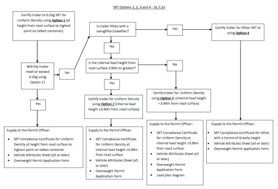
- Download SRT options flowchart (PDF)
1. A Uniform Density SRT overweight permit at the maximum height from the road surface to the highest point on the tallest container (maximum load height of 4.3m).
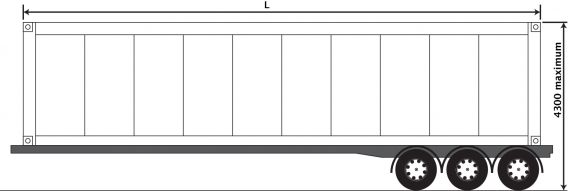
This option is Uniform Density SRT calculated using the weights on the trailer axle set either listed on the Overweight Permit, the Permit Application Form, or at a realistic in-service weight, at the height from the road surface to the highest point on the tallest container, to a maximum height of 4.3m.
As this is the ‘worst case’ scenario it will cover the vehicle for every loading situation within the permit weights and specifically where the composition of the container load is not known.
A valid SRT Compliance Certificate for Uniform Density and using the height from the road surface to the highest point on the tallest container (to a maximum height of 4.3m) completed by an HV Certifier with the HVS2 category, must be supplied with any overweight permit application form. The SRT compliance certificate must be carried on the vehicle and presented to the CVIU on request, together with the standard evidence bona fide listed in Section B3 of the Transport Agency's Vehicle dimension and mass permitting manual.
SRT Compliance Certificates do not have to be done at 22,000kg, as the maximum allowed for a tri-axle set is 21,780kg, depending on axle spacing, and calculating SRT at a higher weight than the permit will allow could lead to the trailer failing to meet the 0.35g compliance target.
Any permit operated outside of its conditions will be revoked under section 5.7 of the VDAM Rule.
Option 1 is recommended for all non-swinglifter/non-sidelifter trailers carrying import containers.
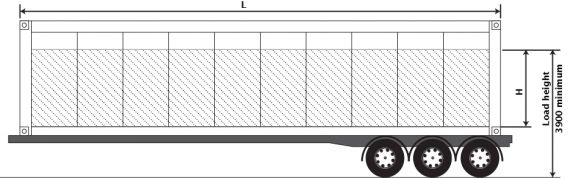
2. A Uniform Density SRT overweight permit with an internal load height of 3.90m or greater (Maximum load/container height 4.3m).
This option is for Uniform Density SRT calculated using the weights on the trailer axle set either listed on the Overweight Permit, the Permit Application Form, or at a realistic in-service weight.
This option can be used where the distance from the road surface to the top of the load in the container is not less than 3.90m (must be 3.90m or more to use this option). This option reflects the fact that most containers have an air gap and are not filled to the roof of the container.
A valid SRT Compliance Certificate for Uniform Density at the permit weights on the trailer and at a minimum load height of 3.90m from the road surface to the top of the load must be completed by an HV Certifier with the HVS2 category and supplied with any permit application form. The SRT Compliance Certificate must be carried on the vehicle and presented to the CVIU on request, together with the standard evidence bona fide listed in Section 8.4.4 of the Transport Agency Overweight Permit Manual.
SRT Compliance Certificates do not have to be done at 22,000kg, as the maximum allowed for a tri-axle set is 21,780kg, depending on axle spacing, and calculating SRT at a higher weight than the permit will allow could lead to the trailer failing to meet the 0.35g compliance target.
The load height will be a condition of the permit. The CVIU have the legal authority to open any sealed container. Any permit operated outside of its conditions will be revoked under section 4.4 of the VDAM Rule.
3. A Uniform Density SRT overweight permit at an internal load height of less than 3.90m.

This option is for Uniform Density SRT calculated using the weights on the trailer axle set either listed on the Overweight Permit, the Permit Application Form, or at a realistic in-service weight.
This option can be used where the distance from the road surface to the top of the load in the container is less than 3.90m. This option reflects the fact that most containers have an air gap at the top of the load, and are not filled to the roof of the container.
A valid SRT Compliance Certificate for Uniform Density at a load height less than 3.90m from the road surface to the top of the load must be completed by an HV Certifier with the HVS2 category and supplied with any permit application form. The SRT Compliance Certificate must be carried on the vehicle and presented to the CVIU on request, together with the standard evidence bona fide listed in Section B3 of the Transport Agency's Vehicle dimension and mass permitting manual.
SRT Compliance Certificates do not have to be done at 22,000kg, as the maximum allowed for a tri-axle set is 21,780g depending on axle spacing, and calculating SRT at a higher weight than the permit will allow could lead to the trailer failing to meet 0.35g.
This option also requires permit applicants to supply an accurate drawing (a “load plan”) which shows the height the container is loaded to (H), the mass of the contents, and the load height of the vehicle. This load plan will need to be carried on the vehicle for inspection by the CVIU.
The load height will be a condition of the permit. The CVIU have the legal authority to open any sealed container. Any permit operated outside of its conditions will be revoked under section 4.4 of the VDAM Rule.
4. An ‘Other’ SRT permit for swing lifter/sidelifter trailers (lifting arms not shown).
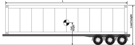
This option is calculated using the weights on the trailer axle set either listed on the Overweight Permit, the Permit Application Form, or at a realistic in-service weight. The load must be calculated on the basis that the contents are uniformly dense, and the CoG of the load itself can be nominated using the “Other” method.
A valid SRT Compliance Certificate for ‘Other’ SRT and at a maximum payload CoG height will be required to be completed by an HV Certifier with the HVS2 category and supplied with any permit application form. The SRT Compliance Certificate must be carried on the vehicle and presented to the CVIU on request, along with the standard evidence bona fide listed in Section B3 of the Transport Agency's Vehicle dimension and mass permitting manual.
SRT Compliance Certificates do not have to be done at 22,000kg, as the maximum allowed for a tri-axle set is 21,780g depending on axle spacing, and calculating SRT at a higher weight than the permit will allow could lead to the trailer failing to meet 0.35g.
The load height and CoG will be a condition of the permit. Any permit operated outside of its conditions will be revoked under section 4.4 of the VDAM Rule.
All of Vehicle option
An “all-of vehicle” option is under consideration. The details of this have not been approved or finalised at this time.
Brake Coded Vehicles
To ensure that all vehicles receiving overweight container permits have sufficient brake capacity to match the weight approved on the permit, even if they are Brake Coded, the Agency has agreed to allow operators to prove compliance by having a HVEK Certifier, using the flowchart below, to confirm the braking capacity of a tri-axle semi trailer. This should mean that the majority of tri-axle semi trailers with a VAI of no more than 1.1 will not require major brake upgrades. Quad-axle semi trailers are to be treated on a case by case basis.
The results of this compliance check are to be included in the PDS for the job and reflected on the Attribute Sheet.
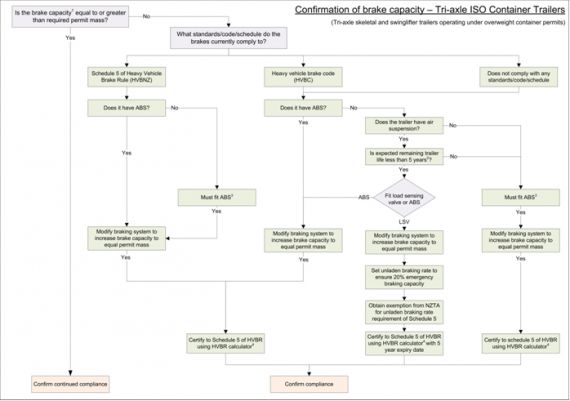
- Download Confirmation of brake capacity flowchart (PDF)
Notes
1. Brake capacity – either the Brake Code Mass for Brake Coded trailers or the brake calculation mass for a trailer complying to the Heavy-vehicle Brakes Rule, (this should be the axle group mass at the GVM for brake rule compliance).
2. If the expected remaining life of the trailer is less than five years and it is fitted with air suspension a load sensing valve can be fitted – the certification of the braking system in this case will have a non repeatable five year expiry date and an exemption from the unladen braking rate in Schedule 5 of the Heavy-vehicle Brakes Rule will be required. This exemption number is to be recorded on the LT400 and the exemption to be carried with the vehicle
3. Load sensing is also an option however it has been demonstrated that this is only suitable for trailers with a tare weight per axle greater than 2500 kg, otherwise compliance in ALL 3 of the required states, unladen, laden, and the emergency braking requirement (20% brake efficiency) typically cannot be achieved.
4. Using a currently approved NZTA calculator, approved ‘proprietary’ software or manual calculations, where approved proprietary software is used compliance to schedule 5 must be demonstrated. The HVBC calculator is no longer approved and can NOT be used.
Vehicle attributes sheet (version 5 or later) required for each truck and trailer from 1 August 2013
From 1 August 2013 all new applications for ISO Container Overweight Permits must be accompanied by a completed Vehicle Attributes Sheet (Version 5 or later) for each truck and trailer signed by an appointed heavy vehicle certifier with the HVS2 category, along with the SRT Compliance Certificates (and a load plan for Option 3) as required in this Memo. All container permit applications received from 1 August 2013 that can prove SRT Compliance using one of the four options and accompanied by a Vehicle Attributes Form (Version 5 or later) signed by an appointed HVS2 certifier for each truck and trailer, that demonstrates the vehicle is being operated within safety limits, will be issued with the full twenty-four month (two year) permit.
Requirements on engineers
When preparing an attributes sheet for an import/export container ‘O’ permit a HVS2 certifier must be engaged to certify the trailer as described in one of the alternatives above and write an LT400. The LT400 is to be added to Landata (IVCERT) but the original SRT values are to be left on the Certificate of Loading. The operator is to be supplied with a copy of the SRT Certificate which must be kept in the cab and produced on request by the NZ Police or NZTA Transport Officers. Such certification is an update and does not replace the original certification.
Where the certifier can verify that the vehicle is unmodified (same dimensions, same axles, same suspension) from its condition when last certified, then the SRT can be updated without physically inspecting the vehicle. Verification can be receipt of a signed declaration from the owner stating that the vehicle is unchanged from its most recent SRT certification. The onus is on the certifier to be satisfied that such a declaration is credible. If it cannot be verified that the vehicle remains unmodified since its last SRT certification then a full inspection and assessment will be required.
When calculating SRT it is important that you use the manufacturer’s values as the generic values are more conservative and may result in a failed SRT. However, when calculating SRT for vehicles using Hendrickson axles (models HT230, Intraax and Intraax AANT) the correct roll stiffness figure is 23,162 Nm/degree (1,327,085Nm/rad). Permit officers have been advised to reject permit applications that use other figures for Hendrickson axles
As an additional assistance it has been agreed that the HVS2 certifier, when calculating the SRT using either option 2 or option 3, may include the tare weight of the container as part of the tare weight of the trailer.
Note that where the SRT has been derived from design data it must be verified from ‘as built’ data prior to the issuing of a SRT certificate.
Summary
- From 1 August 2013 all ISO container permit applications must be supplied with a Vehicle Attributes Form (Version 5 or later) signed by an HV Certifier with the HVS2 category for each truck and trailer, along with the SRT compliance certificates (and a load plan for Option 3).
- Permit applications received after 1 August 2013 with a Vehicle Attributes Form (Version 5 or later) signed by an HV Certifier with the HVS2 category for each truck and trailer along with the SRT compliance certificates (and a load plan for Option 3) will receive 24 month permits.
- All temporary ISO container permits successfully renewed with a Vehicle Attributes Form (Version 5 or later) signed by an HV Certifier with the HVS2 category for each truck and trailer, along with the SRT compliance certificates (and a load plan for Option 3) after 1 August 2013, will be extended from the initial date of issue for the full 24 months at no extra cost.
- SRT compliance certificates do not have to be done at 22,000kg, as the maximum allowed for a tri-axle set is 21,780g depending on axle spacing, and calculating SRT at a higher weight than the permit will allow could lead to the trailer failing to meet 0.35g.
- The Transport Agency will consider on a case-by-case basis extensions of up to one month on the 1 August 2013 deadline for those operators who have been unable to get a certifier to complete SRT compliance certificates. Operators will need to apply to their Permit Issuing Officer in writing.
The Transport Agency is taking this action in response to an increased road safety risk and has been working with industry representatives, the NZ Police and affected vehicle operators as a matter of urgency to inform affected parties what is expected of them. We appreciate your patience and time in addressing these important matters.
Page amended 1 February 2017 (see amendment details).
9 Attributes sheet for HPMV/’O’ Permit
- Download High productivity motor vehicle/ISO permit attributes checksheet v5 (MS Word).
10 Welding in the transport industry 2013
Note that the welder certification standard, AS/NZS 2980:2007, has been superseded by AS/NZS ISO9606: 2017 or AS/NZS 2980:2018, Qualification of welders for fusion welding of steels. Welder certificates to AS/NZS 2980:2007 will not be recognised once they run out and not at all after 1 April 2020. |
Memo 72 - 28 February 2013
Introduction
This document is an update of the publication Welding in the Transport Industry, Version 2 June 1998 ISBN 0478206607 which was produced by the Land Transport Safety Authority (LTSA) for the use of engineers, fabricators and others involved in heavy motor vehicle construction and repair. It outlined the LTSA’s expectations of these people and their organisations. Copyright is held by the NZ Transport Agency.
This document has been revised and updated by the NZTA with assistance from the HVETIG (formerly the RTCE), including the references and Appendices 1-5 and is published in Memo form as an instruction to all HV certifiers.
A guide to key reference documents is included.
Policy for the use of this document
The information in this document is intended to provide useful guidance on manufacture and fabrication of vehicles and components in the heavy transport industry. It can also be used for guidance when undertaking repairs and modifications where welding to the chassis is indicated, but only in cases where the manufacturer allows welding on the chassis or where the manufacturer’s position on welding the chassis is unobtainable. It is NZTA policy that the modifier and repairer must follow the vehicle manufacturer’s instructions and standards (eg as outlined in the manufacturer’s repair and/or body builder’s manual). If the manufacturer does not permit welding, then welding must not be used for modification or repair purposes. In such cases modifications and repairs must be done in accordance with the manufacturer’s instructions, which may mean such modification or repair must not be carried out.
An alternative approach
A chassis can be welded where sound engineering judgement and calculations provide justification even where the OE manufacturer does not support such modification or repair. However, in such cases the HV Certifier takes full responsibility and must be able to support and defend such an approach. At a minimum, substantial reinforcing over the welded section that has been designed to meet the chassis moment of resistance is expected. Such reinforcement would be designed to reduce the cyclic stresses in the weld so that fatigue issue in the welded joint are eliminated. Most manufacturers using a quenched and tempered (QT) chassis provide welding recommendations within their manuals even when their opening statement says that the chassis must not be welded although these welding recommendations are usually supplied as a field repair and assume the affected rail will be replaced at the earliest opportunity. Always look for the manufacturer’s welding recommendations in the first instance.
Applicable standards and weld quality
The applicable welding standard is the joint New Zealand and Australian standard, AS/NZS 1554.1:2011, Structural Steel Welding, Part 1, Welding of Steel Structures (minimum yield strength not exceeding 500 MPa). Superseded standards must not be used.
Other applicable joint standards are:
- AS/NZS 1554.4:2010, Part 4, Welding of High Strength Quenched and Tempered Steels (minimum yield strength not exceeding 1000 MPa)
- AS/NZS 1554.5:2011, Part 5, Welding of Steel Structures Subject to High Levels of Fatigue (minimum yield strength not exceeding 450 MPa)
- AS/NZS 1554.6:2012, Part 6, Welding of Stainless Steel.
- AS/NZS 1665:2004 Welding of Aluminium Structures
Note that the welder certification standard, NZS 4711, has been superseded by AS/NZS 2980:2007, Qualification of welders for fusion welding of steels, and welder certificates to NZS4711will not be recognised once they run out after 1. April 2011.
Choosing the appropriate standard
The choice of standard will depend on the types of steels above to be welded. There are several additional factors that must also be considered when determining the most appropriate standard to use. For example, if the chassis is made from quenched- and tempered-type high strength steel, use AS/NZS 1554.4 Part 4 2010. (see Appendix 2).
For materials which fall outside the range of the standards, follow the manufacturer’s recommendations and develop particular weld procedures, or refer to Appendix 3: ‘Finding out the mechanical properties of the material in the as welded condition’.
Chassis repairs and modifications (general case)
Certifying engineers issuing Design Certificates for chassis or structural manufacture, repairs or modifications have total accountability for fulfilling all statutory and legal obligations concerning such activities. A Design Certificate (Statement of Design Compliance) is a formal declaration that the certifying engineer has fulfilled all such requirements and is accountable for the integrity of the manufacture, repair or modification.
The certifying engineer must:
- Identify the parent metal, and
- Choose the appropriate standards for design and fabrication, and
- Ensure compliance with those standards of all parties encompassed in the certification, and
- Provide evidence of sufficient strength of the welded component.
If the strength of the steel used for the chassis is achieved through the heat treatment of a weldable steel, (eg, some US specification chassis) the certifying engineer must ensure that the design requirements and welding procedure for the modification meet:
1. The original vehicle manufacturer’s specifications, or, if this information is not available
2. The design and fabrication engineering practice as described in this document.
The certifying engineer takes responsibility for the modification or repair, and must satisfy the NZTA that the vehicle has been restored to within safe tolerance of its original structural strength. Requirements to be met are contained in Land Transport Rule: Heavy Vehicles 2004
If, under Section 6.4 or 7.1(2) of the Heavy Vehicles Rule, the chassis rating has ceased to be appropriate because of the modification or repair, the certifying engineer takes responsibility for the modification or repair and must issue a new chassis rating as specified in HVS Certifier Memo 57a (Technical bulletin 4) and subsequent relevant memos.
Chassis modifications for alteration of the chassis rating
When chassis modifications are for the purpose of alteration to the established chassis rating outside the scope of the HV Rule and/or HVS Certifier Memos 57a (Technical bulletin 5) and 57b (Technical bulletin 6) and other relevant instructions, the NZTA will expect, in the first instance, the certifying engineer to obtain approval from the original chassis manufacturer. The manufacturer should recommend a procedure for modification that will sustain the original specifications.
If the modification does not fall within the scope of or meet the Rule or relevant Memos or instructions then the NZTA may impose any conditions deemed necessary, including prohibition, and may alter the vehicle ratings according to the information provided by the certifying engineer, vehicle inspector or Transport Officer.
The NZTA may ask the certifying engineer to provide additional information from the manufacturer or other expert sources (eg Industrial Research Ltd (IRL), Heavy Engineering Research Association (HERA), materials testing agencies) to confirm the safety of the modification.
As with any repairs or modifications, failure to observe the relevant Land Transport Rules, regulatory, statutory requirements and standards, may result in the removal of the chassis rating and the withdrawal of the certificate of loading.
Design and Fabrication
Standard AS 1250:1981 is now superseded. It has been incorporated into the revised and reissued AS 3990:1993 Mechanical equipment – Steelwork. AS 3990-1993 or BS 7608:1993 are the standards to use in all design, fabrication and repair work in the truck/trailer industry. Section 9.8 of AS 3990-1993 requires that all welds comply with AS 1554 which has been updated to AS/NZS 1554.
Auditing
For the purposes of traceability complete documentation must be available to a NZTA audit so that there is a trail of evidence of compliance.
Penalties and enforcement
Failure to meet the legislative requirements may expose:
- The vehicle’s operator to an infringement fee of $150 for operating a vehicle that does not meet the prescribed requirements of Land Transport Rule: Heavy Vehicles 2004 (Rule 31002), and
- The certifying engineer to sanctions up to and including revocation of their notice of appointment, and
- The certifying engineer and others involved in the modification work, who knowingly fail to meet the prescribed requirements, to criminal charges and/or liability.
The prescribed technical requirements will be enforced by the NZTA and the Police. Any vehicle that does not comply with the prescribed technical requirements may be ordered off the road by the Police.
Reference documents
- Current New Zealand Standards are available for purchase from Standards New Zealand: http://www.standards.co.nz
- Land Transport Rules are available for free download from the New Zealand Transport Agency (NZTA): http://www.nzta.govt.nz/resources/rules/about/index.html
- WTIA Technical Note TN01-06 is available for purchase from Welding Technology Institute of Australia (WTIA): http://www.wtia.com.au/catalog.htm
- ‘NZ Welding Centre Report R8-07 High strength steel: Design and fabrication: Appendices: 1992’. Available for purchase from the Heavy Engineering Research Association (HERA): http://www.hera.org.nz
- The Welding Technology Institute of Australia (WTIA) was formed in 1989 by the amalgamation of the Australian Welding Institute (AWI) and the Australian Welding Research Association (AWRA). The AWRA document, ‘Welding Quenched and Tempered Steels’ Technical Note 15 (1985) cited in the 1998 Version of ‘Welding in the Transport Industry’, was renamed WTIA Technical Note 15 and updated as ‘Welding and Fabrication of Quenched and Tempered Steel’ (1996). It is available for purchase from Welding Technology Institute of Australia (WTIA): http://www.wtia.com.au/catalog.htm
- Australian Standards are available for purchase from SAI Global, Australia: http://infostore.saiglobal.com
Appendices
Appendix 1: Definitions AS/NZS 1554
Appendix 1 provides definitions for the ‘Responsible Parties’ referred to in the document AS/NZS 1554 when specifically applied to the repair and manufacture of equipment operating in the New Zealand road transport industry.
Certifier
NZTA appointed Specialist Certifier. In the absence of an Inspector, they are responsible to NZTA for ensuring specified work meets the requirements of NZS 1554.
Fabricator
Person or organisation responsible for the welding (may be the workshop owner).
Inspecting Authority
Organisation with the statutory authority to inspect and certify compliance of welding operators, welding procedures and final welds. A Specialist Certifier who holds appropriate qualifications could fulfil this role.
Inspector
Either a Specialist Certifier who meets the qualification requirements of AS/NZS 1554, or an appropriately qualified person employed by the Inspecting Authority.
Principal
This can be NZTA, the vehicle owner, or the manufacturer. A Specialist Certifier acts as the Principal’s representative.
Report
The minimum requirement upon which to base a written report must be a visual inspection of all welding to be certified as complying to AS/NZS 1554.
Welder
A person who meets the qualification requirements of AS/NZS 1554 for the position and technique of the welding being performed.
Welding Supervisor
A person employed by the Fabricator who meets the qualification or experience requirements defined in AS/NZS 1554. A Specialist Certifier could be delegated this role by the Fabricator.
Appendix 2: Review AS/NZS 1554.5
Appendix 2 details applications of AS/NZS 1554.1 and AS/NZS 1554.5 regarding welds not exceeding/exceeding 500 MPa yield.
For materials not exceeding 500 MPa yield
This applies for welds subjected to fatigue loadings when the stress in the weld exceeds 80% of Category B of AS 3990 (or exceeds the stress range permitted for detail 112 of AS4100 or NZS 3404.1). AS/NZS 1554.1 should be used for all lower levels of fatigue stress.
Examples
80% Category B
Load condition 4 = 0.8 x 110 = 88 MPa | Range (over 2,000,000 cycles)
Load condition 3 = 96 MPa | Range (500000 – 2,000,000 cycles)
Load condition 2 = 148 MPa | Range (100000 – 500,000 cycles)
Reviewing differences between AS/NZS 1554.1 and AS/NZS 1554.5 for materials not exceeding 500 MPa yield: Generally, there are no differences between the two, except for the level of inspection required and levels of imperfections allowable. In broad terms, AS/NZS 1554.5 only allows levels of imperfections which are 50% of the allowable levels of imperfections in ASS/NZS 1554.1.
Materials exceeding 500 MPa yield
If the materials are High Strength Quenched and Tempered Steels, AS/NZS 1554.4 applies. If the stress in the weld exceeds 80% of category B of AS 3990, then this weld is designated FP (Fatigue Purpose). In this case, higher levels of inspection are required and lower levels of imperfection apply.
Appendix 3: As welded material properties
Appendix 3 details methods of Finding out the mechanical properties of the material in the as welded condition.
In the first instance, the certifying engineer must obtain material specifications and procedures from the original chassis manufacturer. If this information is not obtainable from the manufacturer, the certifying engineer must undertake the following course of action:
1. Determine the properties of the unwelded parent metal through a materials testing agency. It may be necessary to test tensile strength, yield strength, elongation, chemical composition and/or hardness.
2. Assess the weldability of the steel, in line with Welding Technology Institute of Australia (WTIA) Technical Note TN1 (2006). Use the weldability group number determined through TN1 when working out possible preheat. HERA recommend that, for practical reasons, only steels with a carbon equivalent of <0.50 (equivalent to Group 5) be considered for welding. If in doubt, seek expert advice (eg HERA, a practising metallurgist etc.).
3. Choose the welding electrode carefully. The choice of a matching strength electrode is only of value if the expected loss of strength in the Heat Affected Zone (HAZ) is insignificant. If in doubt, seek expert advice (eg HERA).
4. Develop and qualify the welding procedure in accordance with AS/NZS 1554.1. If the material is not pre-qualified, the procedure must be qualified by testing. Such cases can be treated the same as when qualifying non pre-qualified consumables for weld category SP. Obtain approval of the procedure by a suitably qualified person (e.g. HERA). The welder can be qualified to the procedure under AS/NZS 1554.1 or to AS/NZS 2980: 2007.
5. Determine the mechanical properties of the material in the as welded condition from the welding procedure test, i.e. tensile, yield, elongation, and (if necessary) impact (charpy) values.
6. Use the mechanical properties determined for the design calculation. Please note:
- the weld strength including the heat affected zone (HAZ) for some of the high strength steel (HSS) chassis rails is typically below that obtained for the unwelded parent metal
- the fatigue strength of a welded detail is always considerably below that of the unwelded parent metal and does not depend on the strength of the parent metal
- remember to specify weld category to AS/NZS 1554 and the extent of non-destructive examination required
- refer to HERA NZ Welding Centre Report R8-07: High Strength Steel; Design and Fabrication, and Australian Welding Research Association (AWRA) Technical Note, Issue 15.
Appendix 4: Industry Standard Weld Procedures
Appendix 4 details some methods to obtain qualified weld procedures.
Compliance with AS/NZS 1554 (all parts) requires that all welding procedures used by workshops must be individualised to the workshop by way of a Macro test examination, as a minimum, provided that all other requirements for qualifying the procedure have been met.
Most welding tasks performed within the road transport manufacture and repair industry can be covered by a clearly defined range of welding procedures. This document supports the use of industry developed standard weld procedures which can be tailored for individual workshops and may be used by workshops without the need for further proving.
Such procedures may be developed by relevant industry groups (HERA, HVETIG, TTMF) for use by their members.
Where these procedures are used when HV Certification is required it must be under the supervision of a NZTA appointed Heavy Vehicle Certifier. Unless specified on a SoDC or other approved engineered solution, the certifier must take responsibility for specifying the procedure to be used and is also responsible for ensuring that the workshop, its equipment and personnel, are capable of meeting the parameters specified in the procedure.
For any tasks that are not clearly covered by available standard procedures a new procedure must be developed and must meet all the requirements of AS/NZS 1554.
Appendix 5: Brittle Fracture Considerations
Appendix 5 is a general discussion on the dangers and affects of brittle fracture.
HVSC’s have a responsibility not to lose sight of potential Brittle Fracture problems throughout the complete design and certification process.
Brittle Fracture is not a matter for welder testing to AS/NZS2980 other than using a test procedure compliant with AS/NZS 1554.1. HV Certifiers are required to specify and ensure any job has been completed in compliance with AS/NZS 1554 pt 1-5. Therefore, with respect to welder testing HV Certifiers need to adopt WPS’s which have been developed to reduce the size and incidence of defects in welds which are a major cause of brittle failure.
The other aspects of Brittle Fracture fall outside the realms of welding performance being material selection for Design Service Temperature, metallurgy, design and design detailing. All aspects that should be fully considered prior to a weld procedure being chosen.
Generally the shape changes (stress risers) and defects that increase the sensitivity of a structure to fatigue failure, also give rise to brittle fracture in notch sensitive materials.
Structures that are designed for fatigue are generally less prone to brittle fracture under normal loading conditions as the structure will be functioning below the notch sensitive stress levels.
In ductile structures the peak stress at a discontinuity or defect in the material, or in a weld, will result in local deformation and a redistribution of the stress tending to average the stress out. Repeated fluctuated loads will eventually lead to fatigue failure.
In a notch sensitive material, the material will tend to fracture rather than deform giving rise to an even higher level of peak stress at the point of the fracture and an increase in stress due to the reduction in section resulting in total failure.
Structures designed for high fatigue sensitivity, for example AS 3990 Category E load condition 3 ( 55MPA nominal stress) would be less prone to failure due to brittle fracture than if designed for load Category E condition 1 (140 MPa).
Towing connections with a design life of 10 year would be more prone to brittle fracture, than if designed for for a 20 year life.
Conclusion
Where a component is designed for a minimum fatigue life of 10 years brittle fracture can be considered to be accounted for by the fatigue design. For any reduction in the design life from 10 years the component will need to be designed for brittle fracture with appropriate material selection. All the welding requirements of NZS 1554 appendix B need to be followed.
High Strength Materials. Special attention must be paid to the fracture toughness when using high strength materials, ie yield strengths greater than 350 MPa. These materials may display good fracture toughness and fatigue properties but may be very prone to embrittlement due to poor welding procedures and may become notch sensitive. For these materials specific welding procedures must be applied and the requirements of NZS 1554 Parts 1 and 5 strictly adhered to.
11 Attributes sheet for 50MAX permit
- Download 50MAX vehicle combination attributes sheet (MS Word, external link).
12 SARN brake data
Category: HVEK
Purpose
- This technical bulletin replaces Memo 86.
- This technical bulletin covers the use of brake data derived from the Australian sub assembly registration number (commonly called SARN data).
Issues
Land Transport Rule: Heavy-vehicle brakes 2006: Schedule 5: Section 11: Clauses 11.1 through 11.3 require brake data to be provided by the axle manufacturer or brake manufacturer and that the data must be based on tests carried out in accordance with one of the standards in 2.5(2) of the Rule. ADR 38 is not one of the standards in 2.5(2).
However, SARN data derived under ADR 38 is being provided, and by organisations other than axle manufacturers or brake manufacturers, and this data is being used for some brake certifications. Feedback from HVEK Certifiers has increasingly highlighted a problem with the brake factor calculated using SARN data as being unrealistically low. HVEK Certifiers then have to come up with a best-guess brake factor, usually by making a comparison with a similar foundation brake, to complete certifications. To use the SARN data unmodified results in errors of up to 30%, resulting in over-braked axles and premature brake lining wear.
Short term solution
Where axle or brake manufacturer brake data is not available but SARN data to ADR 38 is:
- Apply for exemption from clauses 11.1, 11.2 and 11.3 as appropriate
- Derive brake data from a similar (Note 1) foundation brake and use that data
- Obtain confirmation that the friction material on the axle is equivalent to the friction material of the brake in 2.
- Enter appropriate comments on the LT400 and an expiry date of six months at which time the vehicle will require re-certification using correctly established brake data.
This short term solution can only be applied to vehicles fitted with an ABS function.
This approach is available to be applied to exemption applications received from the date of issue of this Memo until 30 November 2016. That is, exemptions will not be granted for applications received after 30 November 2016.
This approach does not need to be applied retrospectively to vehicles already certified.
Long term solution
From 1 December 2016 axle and brake manufacturers and retailers must comply with their responsibilities under Clause 10.5 of the Rule.
Note 1
Geometry needs to be the same (s-cam radius, drum radius, location of shoe pivot points, etc).
Page added 24 May 2016 (see amendment details)
13 Stock crate certification
It is important that stock crate retention is correctly certified to the appropriate standard. This technical bulletin provides explanations of different types of stock crates (fitted to a vehicle with a GVM of 6000 kg or more) their attachments, how to identify them, and how to identify their certification.
References
Stock crate attachment types
There are three common ways that stock crates are attached to heavy motor vehicles:
- J-hook
- Monocoque
- Deck-mounted.
J-hook
The crate attachment is easy to see as the J-hooks sit on the outside (Figure 13-1-1).
Figure 13-1-1. J-hook stock crate
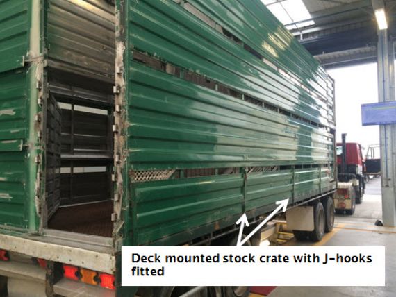
The stock crate is not a vehicle therefore the actual crate J-hook mountings and J-hooks cannot be certified with an LT400. The design can be certified with a design certificate and a plate or label attached to the stock crate.
The design certification for the stock crate anchorage is catered for with an design certificate and the certificate will be held on file by the stock crate manufacturer.
The stock crate identification plate or label needs to have all of the following information:
- Company name
- Serial number
- Date of manufacture
- J-hook capacity load
- J-hook capacity individual
- Number per side.
A certificate of fitness inspector can be satisfied in regard to the certification of the stock crate J-hook mountings if a plate or label providing all the information above is attached to the crate and there is a separate load anchorage certification plate fitted to the vehicle to cover the deck mounting points (coaming rail) used to secure the stock crate.
Monocoque
A stock crate and vehicle constructed as one integral assembly, usually without a rigid chassis, with the wheel and axle assemblies , suspension and steer dolly (in the case of a full trailer) attached directly to the crate assembly. The stock crate fits directly to the chassis and there are no coaming rails or tie rails. (Figure 13-1-2).
Figure 13-1-2. Monocoque stock transfer vehicle
This must be certified to NZS5413.
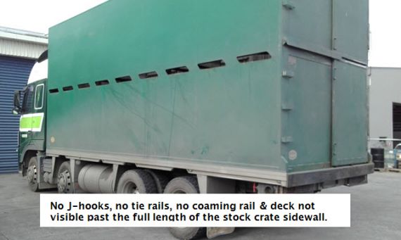
Deck-mounted
Another common attachment is the deck-mounted stock crate. There are no external attachments and the fitment looks very similar to monocoque except that the crate sits on a deck which is visible with a coaming rail and general fitment of load anchorages and tie rails (Figure 13-1-3).
Figure 13-1-3. Deck-mounted stock crate
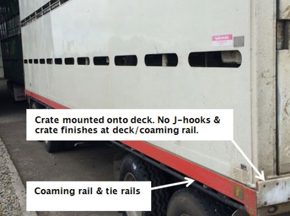
Requirements for certification of deck mounted stock crates.
The stock crate is not a vehicle therefore the actual crate bolt mountings and bolts cannot be certified with an LT400. The design can be certified with a design certificate and a plate or label attached to the stock crate.
The design certification for the stock crate anchorage is catered for with an engineer’s design certificate and the engineers certificate will be held on file by the stock crate manufacturer.
The stock crate identification plate or label needs to have all of the following information:
- Company name
- Serial number
- Date of manufacture
- Restraint capacity load
- Restraint capacity individual
- Number per side
A certificate of fitness inspector can be satisfied in regard to the certification of the stock crate bolted mountings if a plate or label providing all the information above is attached to the crate and there is a separate load anchorage certification plate fitted to the vehicle to cover the deck mounting points used to secure the stock crate.
Sample stock crate plate design
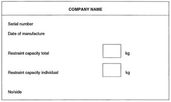
Notes
- Any vehicles inspected after 1/11/2016 that do not meet the requirements but are fit for purpose (inspector has completed a detailed visual inspection and is confident that the anchorage points are in good condition) may be passed for CoF but must have certification completed (in line with this technical bulletin) before next CoF. Notes must be recorded showing the completion of this inspection and actions needed to be taken before next CoF.
- Any vehicles presented for inspection 1 year after 1/11/2016 will not pass for CoF without correct certification.
- All vehicles presented for first time entry compliance must meet these requirements for stock crate/load anchorage immediately.
Page added 14 October 2016 (see amendment details).
Page updated 21 May 2019 (see details)
14 Lost or illegible identification plates for drawbars, drawbeams and towbars
| This technical bulletin replaces memo 25 and memo 51 |
Standards
- Drawbars and drawbeams fitted heavy vehicles must be certified to NZS 5446:2007
- Towbars fitted to heavy vehicles must be certified to NZS 5467:1993.
Certification to these standards requires that components are identified by means of a prescribed ID plate fitted to the component.
Note: These ID plates are an inspection requirement at CoF and are subject to inspection by appointed NZ Transport Agency Transport Officers and NZ Police.
If an ID plate is damaged or lost, it requires replacement. The operator may request a duplicate of the ID plate and the certifier has two options.
Option one
The original certifier must verify the vehicle identity and the drawbar/drawbeam/towbar specifications with the original certification records. The certifier shall also establish that the component has not been modified or repaired since original manufacture and certification. When the certifier is satisfied, they then issue a duplicate identification plate with the same expiry date (if required) and ensure that it is attached to the component.
If the HVSC is satisfied that the vehicle identity and the drawbar/drawbeam/towbar can be verified with photographs, it is acceptable to perform this remotely.
Option two
The drawbar/drawbeam/towbar is re-certified by a HVET certifier in accordance with Re-certification of drawbars & drawbeams of known identity. Replacement is mandatory when the identity of the component is in doubt or the component has been modified or damaged and repaired with no evidence of subsequent recertification.
Page added 9 April 2018 (see amendment details)
15 Documents required for presentation to an IO following HV specialist inspection and certification
| This technical bulletin replaces the 31 series of memos. |
The tables below set out the minimum requirements for documentation to be presented and retained by CoF and entry inspecting organisations before the first CoF can be issued (following heavy vehicle specialist inspection and certification). Where there is insufficient space on the LT400 to record all the applicable information, the heavy vehicle specialist inspectors or inspecting organisations may issue additional supporting documents.
Certification category | Description | Documentation required by CoF inspecting organisation |
|---|---|---|
HVEC, HMCD | Chassis, suspension, steering | LT400 |
HVEC, HMCD | PSV roll over strength | LT400 |
HVEC, HMCD | PSV stability | LT400 |
HVET, HMTD | Towing connections | LT400 |
HVEA, HMAD | Load anchorages | LT400 |
HVEL, HMLD | Log Bolster Attachment Code | LT400 |
HVEK, HMKD | Brake modifications including the New Zealand Heavy vehicle Brake Specification (Schedule 5) | LT400 and copy of brake data/parameters and calculations as applicable |
HVP1 | Swept path certification | LT400 |
HVP2 | Performance-based standards | LT400 |
HVS1, HVS2 | Static roll threshold (SRT) | LT400 and SRT compliance certificate |
Separate LT400 for each Land Transport Rule section or clause, code or standard
An LT400 can only be used for compliance to one Land Transport Rule, standard, or code. A separate LT400 is required for each Land Transport Rule section or clause, code or standard which is applicable to the vehicle in question. That is, the 'Code/Standard/Rule certified to' box must contain only one section or clause of a Land Transport Rule or refer to only one code or standard.
Examples
- A semi-trailer (first trailer of a B-train) that is fitted with a fifth wheel, king pin/skid plate, load anchorages, and log bolsters requires four separate heavy vehicle specialist certificates as in the table below:
Component | Certification category | Code/standard certified to |
|---|---|---|
Fifth wheel | HVET or HMTD | NZS 5450 |
King pin | HVET or HMTD | NZS 5451 |
Load anchorages | HVEA or HMAD | NZS 5444 |
Log bolsters | HVEL or HMLD | Bolster Attachment Code |
- A 4 x 2 truck that has the chassis lengthened, a tag axle fitted, new load anchorages, and a draw beam requires four separate heavy vehicle specialist certificates as in the table below.
Component | Certification category | Code/standard certified to |
|---|---|---|
Chassis or suspension | HVEC or HMCD | Heavy Vehicles Rule (Note 1) |
Brakes | HVEK or HMKD | Heavy Vehicle Brakes Rule (Schedule 5) |
Load anchorages | HVEA or HMAD | NZS 5444 |
Drawbeam | HVET or HMTD | NZS 5446 |
Note 1
Suspension and chassis modifications can only be included on the one LT400 when completed by the same engineer at the same time as part of the same job.
- A bus or coach is manufactured in New Zealand with standards-compliant brakes from the chassis manufacturer, and is fitted with a towbar, passenger seatbelts and a stressed seat with integral seatbelts for the driver then three to five heavy vehicle specialist certifications will be required.
Component | Certification category | Code/standard certified to |
|---|---|---|
Stability or Rollover Strength | HVEC or HMCD | Passenger Service Vehicles Rule (Note 2) |
Towbar | HVET or HMTD | NZS5467 |
Seatbelt anchorages or Seat mounts for seat with integral seatbelt | HVEC or HMCD | Seatbelt and Seatbelt Anchorages Rule (Note 3) |
Note 2
Stability and rollover certifications can only be included on the one LT400 when completed by the same engineer at the same time as part of the same job.
Note 3
Seatbelt anchorages or seat mounts for seat with integral seatbelt certifications can only be included on the one LT400 when completed by the same engineer at the same time as part of the same job.
Note 4
Additional certification will be required if the vehicle is fitted with a tow bar, roof rack, a wheelchair hoist, powered ramp or wheelchair/wheelchair occupant restraints.
Page added 9 April 2018 (see amendment details)
17 Heavy vehicle power pack upgrades to meet emissions requirements
| This technical bulletin replaces memo 59. |
A heavy vehicle entering (or re-entering) service may be repowered to meet the requirements of the Land Transport Rule: Vehicle Exhaust Emissions 2007 by replacing its non-compliant heavy vehicle power pack (Note 1).
Requirements for a repower
- The repower must meet the applicable emissions standard, and
- The repower and its installation must be to the specifications and instructions of the manufacturer of the power pack for the application or be an alternative approved by the vehicle manufacturer, and
- Where final drive or other installation conditions are specified by the manufacturer, they must be met and noted in the final certification, and
- The repower is to be certified by an HVSC with the chassis (HVEC) category, confirming that it meets all the above requirements, and
- Supporting documentation from the power pack or vehicle manufacturer must be available.
Note 1
Power pack means the engine, its radiator/cooling pack, induction and exhaust systems (including layout), and any accessories or emissions control equipment (such as add blue) specified by the manufacturer.
Note 2
In-service repowers, whether considered modifications or repairs, are not affected by Land Transport Rule: Vehicle Exhaust Emissions 2007.
Note 3
If an engine or power pack is replaced by a unit by the same manufacturer, part number, specification and emission standard then it is considered a repair and not a modification and is not affected by the requirements of the Rule.
Page added 9 April 2018 (see amendment details)
18 Rebirthing
| This technical bulletin replaces memo 80. |
Rebirthing is the practice of issuing a new VIN to an existing vehicle. It often manifests in attempts to give new life to old vehicles or vehicle components. Rebirthing is illegal and is not approved by the Transport Agency.
- A VIN remains for the life of a vehicle even if the vehicle goes through a number of iterations. It is essential that the vehicle history is maintained.
- During a vehicle’s life, it may have replacement chassis rails, axles, towing connections or even styles of towing connections or number and/or location of axles. These modifications do not create a new vehicle.
- A vehicle cannot be rebirthed with a new VIN. A VIN cannot be altered (including the removal of a VIN).
Recertification after repair/modification
Depending on the level of repair and/or modification, compliance may need new certifications. Required certifications could include brakes, chassis, towing connection and load anchorages, depending on the level of repair/modification and how much of the previous certifications could be carried over.
A full chassis replacement is a significant modification and all certifications would need to be redone. If existing components were reused, any recertification would have to take into account any fatigue life already used. The model (and chassis rating/GVM) must be updated in LANDATA. This is achieved by completing a MR16 form and submitting it to the Transport Agency.
The only situation where a vehicle could be classed as a new vehicle (new VIN) would be if the original vehicle had been scrapped and removed from the register prior to beginning the new vehicle build. In this case a vehicle, to a new design, could be built using components from the previously de-registered and scrapped vehicle. All new certifications to the latest requirements would be necessary although, as previously stated, residual life would have to be considered for any second hand components used.
Deregistering, modifying and reregistering does not meet the test of being a new vehicle. The ‘donor’ vehicle must be scrapped if components are to be reused in a new vehicle.
Page added 9 April 2018 (see amendment details)
19 Tightening or reusing bolt-in tow eyes
| This technical bulletin replaces memo 83. |
In the case of an incorrectly fitted or maintained bolt-in tow-eye, the large number of stress reversal tension and compression cycles they are subjected to can cause thread pitches to become worn, loosening the coupling shank or nut. This in turn allows the nut to be pulled over the thread on the shank which causes the towing eye to pull out of the drawbar, resulting in the trailer becoming detached.
Failures to bolt-in tow eyes most often occur within days of the tow-eye securing nut being re-tightened.
HVSC requirements
When involved in the repair or recertification of draw bars fitted with bolt-in tow eyes, the HVSC must take the following into account:
- Tightening the nut of a loose bolt-in tow coupling is not acceptable and may increase the potential for earlier catastrophic failure. The complete towing eye and nut must be replaced.
- If there is any sign of it being loose (eg fretting, shiny, rusting, etc) the tow-eye and nut must be replaced – under no circumstances is it to be tightened.
- When the tow-eye and nut is replaced, the nut must be torqued to the manufacturer’s recommendation (including a greased thread) and then if necessary taken to the next castellation – in no circumstances backed off.
- Instructions should be given to the operator so that following initial installation; the nut should be re-torqued at the lesser of 5000km or as directed by the manufacturer. If it moves it must be re-torqued (Note: this is the only time that re- tightening is permitted).
Inspection requirements
Evidence of looseness of the securing nut, split pin or washer, including wear marks or fretting or evidence that the original nut has been re-tightened are stated as reasons for rejection in this manual and also the VIRM: In-service certification.
- See also the Transport Agency's Safety alert: Bolt-in tow-eye security
Page added 9 April 2018 (see amendment details)
20 Modifications to truck cabs
This technical bulletin provides guidance to heavy vehicle specialist certifiers regarding modifications to trucks’ cabs to ensure compliance with land transport legislation. It’s also expected to serve as a reference for modifiers and importers of modified trucks.
1. Background
It is common practice to modify the cab of a truck to produce a crawl-through or walk-through between the truck’s cab and a custom-made body. Typical examples are motor caravans, truck buses, horse trucks, and other similar special purpose vehicles.
The three critical elements of crashworthiness are the structural integrity of the vehicle (cab), residual space for occupants, and restraint systems. A truck’s cab provides fundamental protection to occupants in the event of an accident.
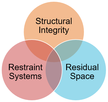
Figure 20-1-1. Three critical elements of crash worthiness
Research and testing have found that even relatively minor modifications to truck cabs can significantly reduce their structural integrity. In the event of a crash, this reduction in structural integrity undermines the survival space for occupants and performance of occupant restraint systems.
In addition to frontal impact protection, modern truck cabs also have inherent structural integrity providing occupant protection from roof loads and side loads (a load applied approximately perpendicular to the longitudinal axis of the vehicle), as to be expected in a truck rollover.
This guidance is primarily aimed at bespoke modifications, not mass-produced variants. Physical testing would result in a damaged cab so is not an option and full engineering analysis of a single modified truck cab can not be done within the financial and time budget restrictions of most conversions.
To that end, common modifications have been reviewed, tested, and recommendations made to produce these general guidelines as a reference for bespoke modifications.
Notwithstanding, the methodology covered here could be applied to series-produced vehicles, where the initial cost of full engineering analysis could be amortised over the series.
2. Legal requirements
The Land Transport Rule: Vehicle Standards Compliance 2002 requires that a modification to a vehicle must result in that vehicle being safe to be operated, designed and constructed using components and materials that are fit for their purpose, and within safe tolerance of its state when manufactured or last certified as a modified vehicle.
Safe tolerance is a defined term and means the tolerance within which the safe performance of the vehicle, its structure, systems, components or equipment is not compromised, having regard to any manufacturer’s operating limits.
The principal that vehicles remain within safe tolerance of their state of manufacture is known as continued compliance.
After modification, the demonstration of continued compliance with only one aspect (such as roof loads, for example) does not validate the inherent, as-manufactured performance of the cab under other loads, such as side loads, for example.
In all instances a vehicle modifier should involve a heavy vehicle specialist certifier in a modification project from the beginning of the project. Failure to do so may result in added costs and delays resulting from the certifier’s obligations.
In summary, there are two primary responsibilities of a specialist certifier in respect of cab cut-outs;
- Inspection of the modifications to ensure they were designed and constructed using components and materials that are fit for their purpose.
- It is highly recommended that the specialist certifier be provided access to the in-progress vehicle, or other verifiable means of documentation. Otherwise, the trim may be damaged during the course of this mandatory inspection.
- Demonstration that, after modifications, the safety of the occupants has not been compromised, having regard to the level of safety the occupants had in the as-manufactured, unmodified cab.
Note: manufacturers’ body builder’s guides commonly feature sections describing where cuts should be made when work is required. While these guides are useful for describing where to (and more importantly, where not to) cut, unless specific guidance for how to reinstate the integrity is described, they must not be considered a replacement for these guidelines. Instead, they should be read in conjunction with these guidelines.
3. Testing overview
To understand how modified cabs performed compared to OEM, the Agency engaged Sandbox Consulting to conduct testing on typical modifications to truck cabs of different GVM ranges. The cabs were tested with the following modifications:
- Modifications to the rear wall only
- Modifications to the rear wall and roof where the structural rings of the cab have been removed
The comparative performance of the cabs demonstrated the relative stiffness of the cabs under loading and the limits at which plastic hinging occurs. After plastic hinging, further loading would continue to deform the cabs, without significant resistance. In the final test of each cab, they were loaded until the cab structure impinged into the approximate residual space of the occupants.
3-1 Modifications to the rear wall only
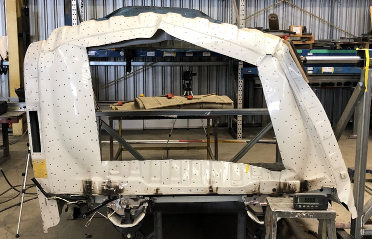
Figure 20-1-2. Modifications to the rear wall only, Japanese (after testing)
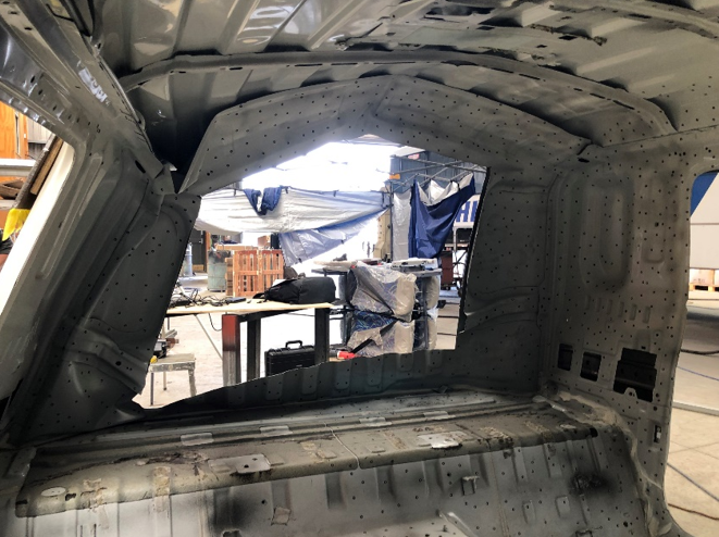
Figure 20-1-3. Modifications to the rear wall only, Japanese (internal, after testing)
3-2 Modifications to the rear wall and roof where the structural rings of the cab have been removed
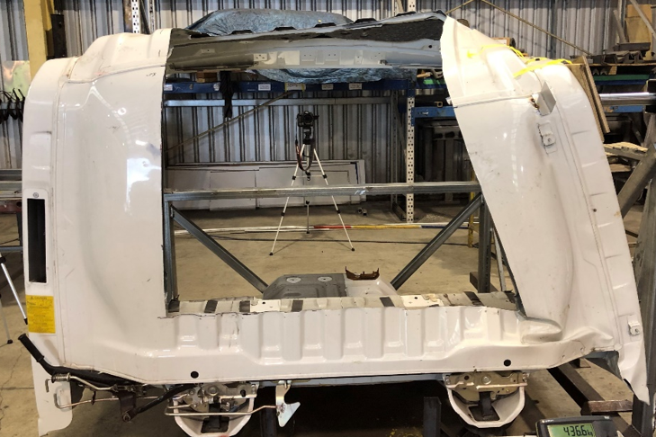
Figure 20-1-4. Modification to the rear wall and roof, Japanese (during testing)
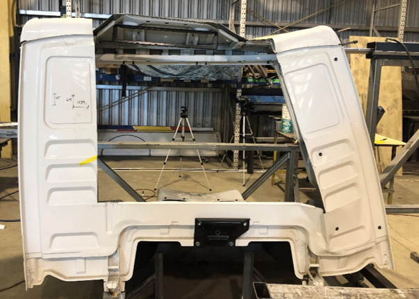
Figure 20-1-5. Modification to the rear wall and roof, European (during testing)
4. Test results
4-1 Strain energy
The results are reproduced using a load-deflection curve (refer to Hooke’s Law). When force is applied to a structure it deforms and stores potential energy. The strain energy is the potential energy stored due to the deflection. Up to the elastic limit, the strain in the structure is also elastic and will be recovered when the load is removed (i.e. the material returns to its original length). However, if the material is loaded beyond the elastic limit, a permanent deformation in the material will take place, this is referred to as plastic strain. The plastic strain of the structure is necessary to achieve energy absorption.
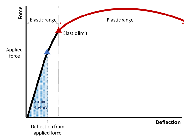
Figure 20-1-6. Load-deflection curve
The area under the curve can be related to the strain energy (work done) and the slope of the curve to the structure’s stiffness. The stiffer a structure is, the steeper the force-deflection curve.
4-2 Cab comparison elastic range
Several tests were performed on each cab with the different modifications in the elastic range. The final test loaded the cab structures past the elastic limit and into the plastic range.
The results of all the tests in the elastic range are shown in Figure 20-1-11, including the curve gradients and linear regression values. Linear regression is a statistical method that allows one to summarise and study relationships between two continuous (quantitative) variables. The results show a strong linear (proportional) relationship between force and displacement in the linear elastic range (as expected). The close clustering of data points between tests shows repeatability of the experimental setup. The difference in maximum load capacity between the Japanese and European cabs is primarily due to the size of truck to which they were fitted (i.e. different GVMs).
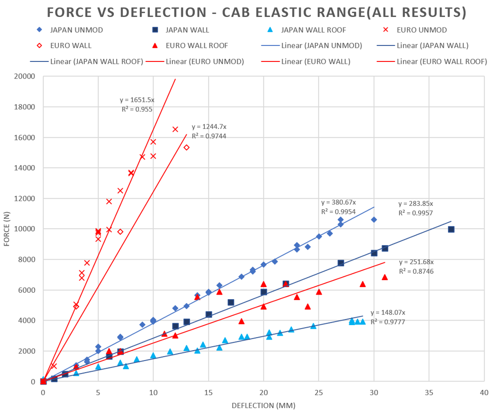
Figure 20-1-7. Force deflection curve elastic range
4-3 Summary of results – elastic range
The results show the cab elastic stiffness is significantly reduced by the modification of the cab structure.
For the Japanese cab, the modification to the rear wall resulted in a stiffness reduction of 26%, while the combined modification to the rear wall and roof resulted in a 61% reduction.
For the European cab, the modification to the rear wall resulted in a stiffness reduction of 25%, while the combined modification to the rear wall and roof resulted in an 85% reduction.
The large difference between the Japanese cab and European cab after the combined modification to the rear wall and roof is due to the design philosophies used by the manufactures, particularly;
- The style of reinforcement used in the rear wall of the cabs, and
- The height differences between the cab (the European cab was higher), and
- Subfloor reinforcement in the Japanese cab.
Note: the cab test results are not intended to be a statement about the manufacturers or country of origin. The tests were carried out to determine the effect of modification to truck cabs.

Figure 20-1-8. Force vs deflection Japanese cab - plastic deformation test
4-4 Summary of results - plastic range
In the plastic loading phase of the testing, several more complicated behaviours were observed, these included the failure of welds, tearing of material, and crumpling of the cab side wall (localised buckling).
Due to the limited availability of identical cabs for testing, the unmodified cab was not loaded to the same level as the one modified with the rear wall only or the one with the rear wall and roof modifications. The test was stopped when significant plastic deformation had occurred.
5. Reinforcement types
When considering how to return the level of occupant protection to within safe tolerance of the cab’s state of manufacture, there are two main options; integrated reinforcement and an independent protective structure.
5-1 Integrated reinforcement
Integrated reinforcement is where the truck cabin and reinforcing structure are directly connected using permanent fixings, as illustrated below.
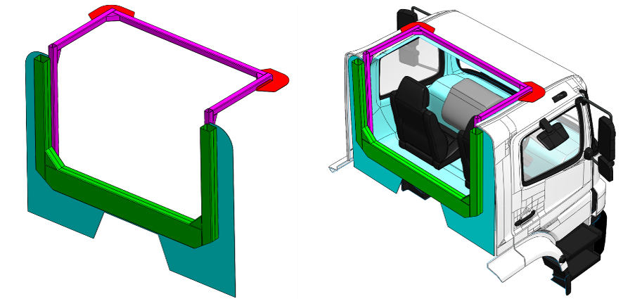
Figure 20-1-9. Example of integrated reinforcement for a rear wall and roof cutout
5-2. Independent protective structure
An independent protective structure is one where the truck’s cab is independent of the protective structure (not permanently attached). This configuration is typically found in truck bus conversions where the structural reinforcements in the body necessary for meeting the PSV Rule provide protection for the occupants of the cab.
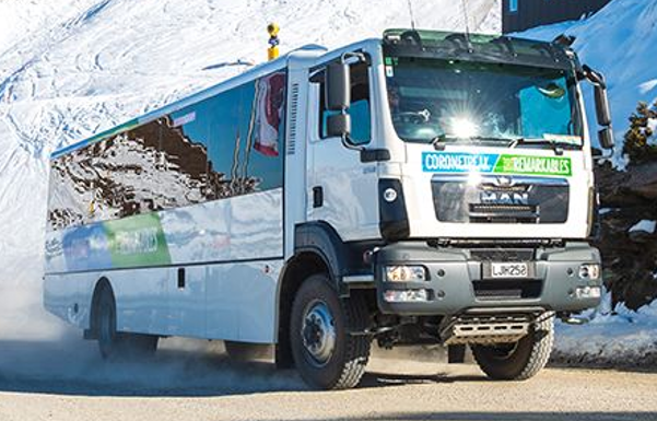
Figure 20-1-10. Typical New Zealand truck bus
(image courtesy NZ Ski)
In situations where it’s appropriate or necessary to make an independent protective structure, it must be shown that:
- The deflection of the body’s protective structure provides adequate protection to the truck cab, and
- The structure must be adjacent to the area of modification (rear wall cut out, with protective frame directly behind), and
- The modification only reduces the strength or stiffness of the cab by less than 25% (e.g. modifications such as enlarging the rear window area but not cutting into the main ring frames of the cab structure), and
- The modified cab structure together with the protection provided by the independent protective structure provide protection for occupants of the cab within safe tolerance of the cab alone when new, and
- The body attachment is fit for purpose.
6. Engineering analysis
In all cases, the engineer must ensure the seatbelt anchorages, seat anchorages, safety systems, and frontal impact performance of the cab is not undermined.
6-1 Modification ‘traffic light’
The engineering analysis required depends on the extent of the modifications. The engineering solutions increase dramatically in complexity from left (‘green’) to right (‘red’), below. Only those certifiers with demonstrated expertise in nonlinear finite element analysis should engage in certifications toward the amber and red side.
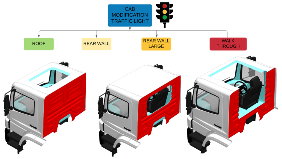
Figure 20-1-11. Cab modification 'traffic light'
Amber and red indicate higher levels of complexity of engineering analysis.
6-2 Cab modification design methodologies
A modern truck cab is designed to absorb and dissipate the ensuing energy of an impact around the body of the cab. Particular attention is required to balance the thickness and stiffness of a reinforcing frame and the parts of the cab to which it is attached. As an energy-absorbing system, overbuilding or over-reinforcing the cab may lead to an unsafe condition.
As noted previously, to demonstrate that a modified cab is returned to within safe tolerance of its original condition, the certifier must show the truck cab performs in a similar way after modification as it did when manufactured to any reasonable load case, including side loads.
6-3 Using UN/ECE Regulation Number 29 (‘R29’) as a benchmark
R29 sets the requirements for occupant safety in the United Nation Economic Commission for Europe (UN/ECE) countries. The standard has become ubiquitous in the truck manufacturing industry both in and outside of Europe. Most truck cabins imported into New Zealand now comply with R29.
To pass R29 a cab may not undergo deformation dangerous to the occupants (penetration into the survival space) when subject to the required test loads. The R29 test uses a pass/fail criterion of survival space large enough for an occupant, so it is the extent of local deformation that is crucial because if any one part of the structure intrudes into this space, the test is failed.
During tests, illustrated below, the components by which the cab is secured to the chassis may be distorted or broken, provided that the cab remains attached to the chassis frame. None of the doors shall open during tests, but the doors shall not be required to open after testing.
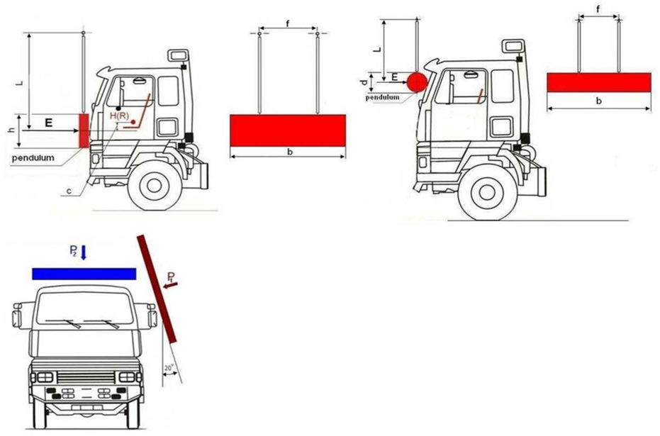
Figure 20-1-12. Impactors from UN/ECE Reg. No. 29 Rev 2.
For industry consistency, either a dynamic load with the R29 impactor, or a quasi-static load using the R29 impactor angles is recommended to use for engineering analysis.
In determining the inherent strength of cabs to side loads, the R29.03 series of amendments are recommended to be used as a benchmark (even if the cab complied with a previous version of the standard which did not include a side-loading test, or another standard).
For the avoidance of doubt, for the comparative analysis, it’s not expected that the modified cab will be capable of demonstrating full compliance with the requirements of R29.03. Instead, it’s a useful benchmark to compare the relative performance between the unmodified and the modified cab to ensure the modified cab is within safe tolerance of its state of manufacture.
6-4 An iterative approach to solving the problem
Finite element analysis (FEA) should be used to justify the modification to truck cabs. A satisfactory result is reached when it can be shown that the force-deflection curves are within safe tolerance comparing the modified to the unmodified cab. The finite element analysis should be done following best practice and include a mesh sensitivity study. Any geometry simplifications (excluding omission of minor features) of the structure should be noted and justified. The flowchart, below, illustrates an iterative approach that can be employed.
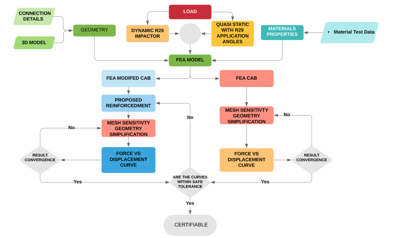
Figure 20-1-13. Process flowchart
There are no appropriate methods available for hand calculation when an integrated approach is taken, with the exception of modifications to PSVs which must comply with the PSV rule.
The following recommendations are made for suitable FEA software:
- The computer software and model must be capable of describing the real physical behaviour of the system under load, ie non-linear plastic collapse. Hand calculations won’t work.
- The model must be constructed, and assumptions prescribed, in such a way that the calculations give conservative results. The engineer should obtain enough material data to support material assumptions used in calculations or models for the areas where the reinforcement and cab are connected, and which are part of the computer model.
- Shell elements are the most suitable method to represent the structural elements used to construct a cab.
- Only materials of known properties may be used for the construction.
- Non-metallic materials may be used; however, the aggregate strength of the system must be demonstrated using physical testing.
- A mesh sensitivity study should be used to demonstrate convergence. Mesh resolution should be appropriate for areas in large deformation areas and around stress concentrations.
- Connections should be modelled appropriately (e.g. spot-welds, bolts and rivets, etc.).
- Glues may be used but physical testing is required to demonstrate aggregate strength.
- The calculations must include an allowance for deterioration during the expected life of the vehicle where appropriate, having regard to the material of the structure, the specific manufacturing technology, and conditions under which the vehicle is likely to be operated.
7. Welding Standards and Material Data
7-1 Cab body welded connections and material
The material properties for cab panels and their weldability are often difficult to obtain from the manufacturer. Different trucks vary in construction methodology and material choice.
The materials used to construct truck cabs range from mild steel (180 MPa), high strength steel (HSS) to ultra-high-strength steel (UHSS - 1500 MPa). A single cab is often made up of a mixture of different materials.
The use of advanced high-strength steels (AHSS), which are thinner, lighter, stronger and have superior performance absorbing impact energy, is increasing. The use of these materials in truck cabs raises concerns about identification, characteristics, where they are used in the cab and to what extent they can be repaired or modified. If not identified by the manufacturer, it is recommended that a certifier conclusively identifies the material.
7-2 Welding to the cab
Generally, the welding process and material specification of the cab panels falls outside the scope of NZS 1554 and the AS/NZS 2980 and AS/NZS ISO 9606.1 welder qualification.
Due to this, the certifier should use welding processes and consumables specified by the vehicle manufacturer for repair or replacement of body panels where available (panel beaters guide or specifications). In some cases, general provisions are provided; however, care must be taken to ensure these apply to the specific panels affected or part of the welded connection.
Plug weld size and spacing and seam weld length may be referenced to determine the connection of additional reinforcements.
If the material and welding information is not available, the certifier may:
- Obtain material test certificates, from suitability accredited test laboratory, for the parts of the vehicle body used in the welded connections and computer models. The material test should include material properties and information relating to weldability.
The test data from a single cab of the same make and series may be used to support the certification of multiple vehicles. However, the certifier must have records to show the cabs are identical and are common to all models in the same GVM range.
Welding should be performed by welders qualified by a recognised industry qualification used in light vehicle repair such as I-Car.
7-3 Welding of reinforcements
In all cases the certifying engineer must:
- Identify the parent metal, and
- Choose the appropriate standards (only current versions of the standards may be used) for design and fabrication, and
- Ensure compliance with those standards of all parties encompassed in the certification, and
- Provide evidence of sufficient strength of the welded component.
The following welding standards may be applicable for the welding/fabrication of the reinforcement structure:
- AS/NZS 1554.1, Structural Steel Welding, Part 1, Welding of Steel Structures (minimum yield strength not exceeding 500 MPa)
- AS/NZS 1554.4, Part 4, Welding of High Strength Quenched and Tempered Steels (minimum yield strength not exceeding 1000 MPa)
- AS/NZS 1554.5, Part 5, Welding of Steel Structures Subject to High Levels of Fatigue (minimum yield strength not exceeding 450 MPa)
- AS/NZS 1554.6, Part 6, Welding of Stainless Steel.
- AS/NZS 1665 Welding of Aluminium Structures
- AS/NZS 1554.7 Structural steel welding of sheet steel structures
7-4 Boron alloyed
The UHSS alloyed with boron is at the higher end of the advanced metals used in truck cab construction.
Parts made from UHSS alloyed with boron should not be straightened or reformed. The steel panels are formed at extremely high temperatures and are prone to work hardening and cracking if damaged or deformed.
Boron UHSS is weldable, and either the GMA (MIG) welding process or squeeze-type resistance spot welding can be used. To maintain the high strength characteristics of the steel, it is important to limit the heat-effected zone.
Information relating to the different issues may be found from industry organisations such as I-Car.
7-5 Material data
The engineer should obtain enough material data to support material assumptions used in calculations or models for the areas where the reinforcement and cab are connected, and which are part of the computer model.
Where the manufacturer specifies a welding process for the area involved in the modification, the material test data may be limited to the tensile test report.
7-6 Alternative materials
Several truck manufacturers use alternative materials for the construction of cab components such as fibre reinforced composites (FCR) or aluminium.
If these components form part of the strength of the cab the engineer must demonstrate any modifications return them to within safe tolerance of their original manufacture, considering the aggregate strength of the materials and connections between components.
7-7 Rivets and bolted connection
The use of rivets and bolts is allowable provided the certifier can show the fasteners have enough bearing area and strength and do not suffer from tear-out. Only structural rated rivets and high tensile bolts should be used. It is recommended that an adhesive system is used in conjunction with bolted and rivet type connections.
7-8 Adhesive joints
The use of adhesives in the connection of reinforcement may be beneficial if not prudent. The use of adhesive in joints provides the following advantages:
- Helps to reduce the stress concentration found in bolded, riveted and welded joints.
- Eliminates sudden changes in stress.
- Shock and impact characteristics of the joint are improved.
- Allows joining of dissimilar materials
- Adhesives can contour and form to complex surfaces.
The engineer, depending on an adhesive joint, must be able to demonstrate:
- A prequalified adhesive system was used, and all requirements in product data sheets were met in the application and use of the product – substrate preparation, adhesive thickness, the temperature and humidity.
- Calculations for the adhesive joints include the expected stress in service and as an occupant protection structure – specifically the orientation, magnitude and frequency of applied loads.
- A test sample is used to validate the connection.
- A suitable factor of safety is used in the design of the adhesive joint considering:
- Adhesive properties
- Environmental conditions
- Fatigue
- Appropriate allowance for deterioration during the expected life of the vehicle.
An adhesive system should be used in conjunction with mechanical rivets or spot welding.
8. Additional Considerations
8-1 Steel grain direction
Folded sheet steel subjected to dynamic high-stress loads can tear along folds. Careful attention must be paid to grain or rolling direction when bending high-strength metals, especially when resulting in small inside bend radii. In steel, the ductility in the direction of rolling is almost twice that at right angles to the direction of rolling. When bending high-strength materials, the part should be orientated so that it can be bent against the grain. Bending with the grain may result in cracking or even breaking in the deformation area.
This attention to grain direction should be noted on engineering drawings.
The direction refers to grain fibre following the direction of rolling and parallel to edges of strip or sheets. To bend across the grain is to bend at right angles to the direction of rolling; to bend with the grain is to bend parallel to the direction of rolling.
8-2 Body attachments
In cases where the truck cab to chassis attachments are modified or replaced with rigid attachments, the attachments should be suitable to maintain the cab structure on the vehicle under the specified loads in the design section of this guideline; this is part of the cab’s compliance.
Additional induced loads on the chassis and cab structure due to the rigid mounting must be considered and justified.
8-3 Restraints and airbags
The engineer must demonstrate that the level of modification has not undermined the function of the seatbelts, seatbelt anchorages or airbags.
8-4 Exhaust systems
The certifier must ensure that the vehicle exhaust system gases cannot enter the passenger compartment.
8-5 Corrosion protection
Adequate coating and corrosive protection of the cab after modification must be applied to reduce the likelihood of deterioration of the cab structure.
8-6 Durability considerations
Consideration must be given to the modification’s impact on the durability of the cab and associated components.
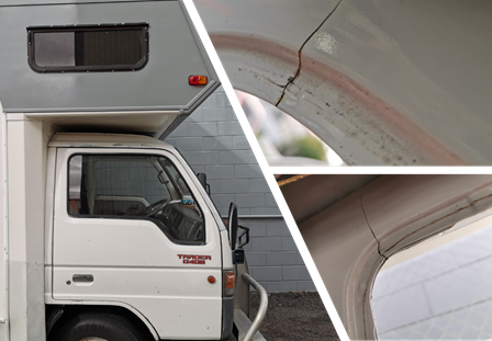
Figure 20-1-14. Cracks developing due to insufficient reinforcement after cab modifications
8-7 HV engineer certifiers and HV manufacturer certifiers
Certifying engineers issuing a Statement of Design Compliance (SoDC) for cab/body modification or repairs which affect the occupant protection have total accountability for fulfilling all statutory and legal obligations concerning such activities.
A SoDC is a formal declaration that the certifying engineer has fulfilled all such requirements and is accountable for the integrity of the manufacture, repair or modification.
Refer to section 11 Local manufacturing for requirements of HV manufacturing certifiers.
Page added 11 August 2020 (see amendment details)