Technical bulletins (general)
-
1 Quick noise check procedure
-
2 Inspection for corrosion in Nissan Terrano and Mistral rear floorpan assemblies
-
3 Detecting wear in spring-loaded ball joints
-
4 Jacking points for common suspension types
-
5 Webbing clamp seatbelts in class MA vehicles
-
6 Inspection requirements for temporary vehicle imports
-
7 Guidance for vehicle inspectors when checking tyre tread depth
-
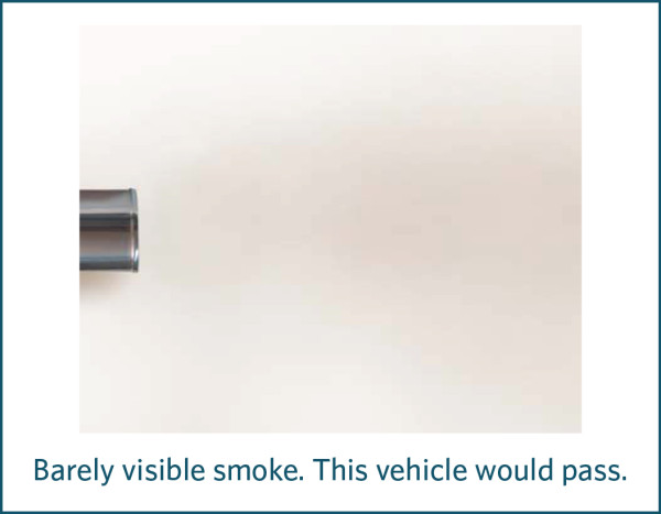
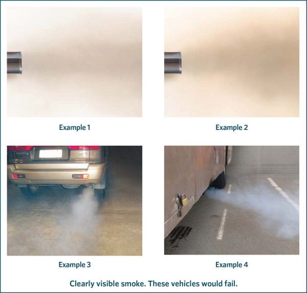
8 Guidance for vehicle inspectors when inspecting vehicles for clearly visible smoke
-
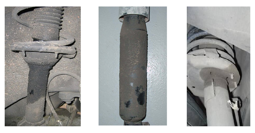
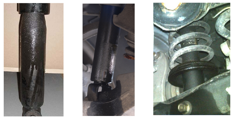
9 Shock absorbers – misting vs excessive leakage
-
10 Brake test procedures for specific vehicles
-
11 Electronic stability control identification
-
12 Used imported vehicles from Japan – disconnected airbags at WoF inspection
-
13 Acceptable overseas proof of modification
-
14 LED light bars
-
15 Identifying compliant hitches and brake systems
-
16 Seatbelt repair and re-webbing
1 Quick noise check procedure
Reference
What is the purpose of the Noise Quick Check?
The purpose of this test procedure is to enable vehicle inspectors to carry out an exhaust noise check with an acceptable noise meter to ensure that vehicle exhaust systems that have been modified to be noisier than OE remain well below the maximum noise levels specified in law (ie be below the noise limits specified in the VIRM). Any vehicle that fails the Noise Quick Check needs to be made quieter and reinspected and/or referred to an LVV certifier for an Objective Noise Test (ONT).
This quick check test procedure is therefore a simplified version of the ONT to ensure results are comparable to the ONT.
What type of vehicle can be tested?
The quick check may be applied only to a vehicle of class LC, LD, LE, MA, MB, MC, MD1, MD2 or NA that is louder than when it was manufactured with its original exhaust system.
Test site specification
The test environment must be such that exhaust noise readings can be achieved as accurately as possible with as little interference from other noise sources as possible.
To achieve this, the test site must, within at least a 3m radius from the noise meter microphone:
1. be an open outdoor site (if this is not practicable, a canopied site may be used provided the canopy is at least 3m above the microphone)
2. be predominantly flat
3. be free from large sound-reflecting surfaces, including buildings, walls, billboards, vehicles, canopy/roof supports, trees or shrubs
4. have a solid surface, such as concrete or asphalt, that is free of any loose or sound-absorbing material.
It is important that a noisy background, eg due to road traffic or wind, is avoided. If in doubt, use the noise meter to measure the background noise either before or after the Noise Quick Check. The background noise must be at least 10dBA lower than the relevant exhaust noise limit specified in the VIRM. Sharp noise interference such as car doors slamming or loud footsteps must also be avoided to prevent false readings.
Which noise meters are acceptable for this test?
The noise meter must be of ‘Type 1’ or ‘Type 2’ (Class 1 or 2) standard to ensure accuracy. The noise meter specifications and a list of other equipment required for noise testing is available here.
The noise meter must be in good operating condition and be maintained within manufacturer’s specifications. Regular calibration is required. Make sure you know how to use it correctly by following the manufacturer’s instructions.
Note 1
The NZTA does not currently intend to make it mandatory for inspecting organisations to obtain a noise meter. However, if you are often presented with noisy vehicles, we strongly recommend that you have one available.
Vehicle preparation prior to testing
Before the noise test can be carried out, the vehicle must:
- have its engine at normal operating temperature
- be stationary with park the brake applied
- have the gear selector positioned in neutral (manual) or park (automatic)
- have the air-conditioning system turned off
- have the engine bonnet closed.
Setting up the microphone for testing
1. Ensure the microphone is fitted with the foam wind shield.
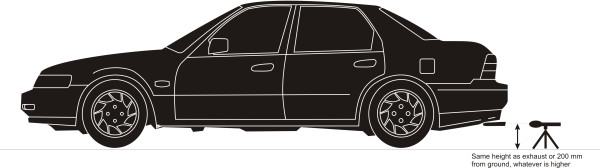
2. Height of microphone
- Mount the noise meter to the tripod. Place it on the ground with the centre of the microphone at about the same height as the centre of the exhaust outlet, but no lower than 200mm from the ground. Make sure the microphone is level, regardless of the angle of the exhaust outlet.
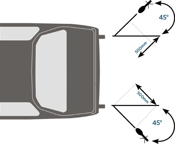
3. Distance of microphone from exhaust outlet
Distance of microphone from exhaust (outlet to the rear)
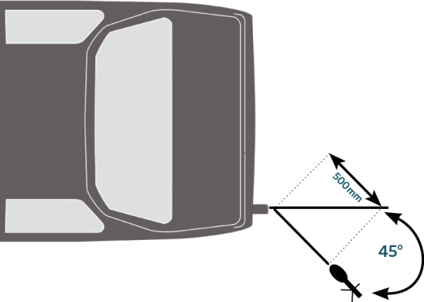
- Position the noise meter 500mm from the exhaust outlet at 45 degrees outboard to the longitudinal centreline of the exhaust outlet.
Distance of microphone from exhaust (outlet to the side)
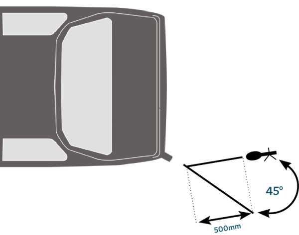
- If the exhaust outlet is at the side of the vehicle, position the noise meter 500mm/45 degrees where it is the furthest from the engine.
Distance of microphone from exhaust (outlet underneath vehicle)
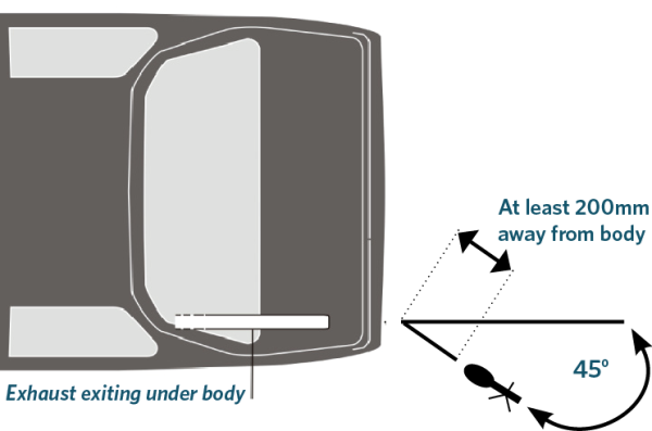
- For exhaust outlets terminating underneath the vehicle body, fit as close as practicable, but no closer than 200mm to the vehicle body. The 45 degree angle may be reduced to ensure a clear path between the microphone and the exhaust outlet.
Distance of microphone from exhaust (two outlets)
- If the vehicle has two exhaust outlets less than 300mm apart, treat them as one outlet with the microphone positioned at the outside outlet. If the two exhaust outlets are more than 300mm apart, measure each one, with the higher of the two taken as the noise level for the vehicle.
Select the test engine speed
Select the appropriate test engine speed from the table on the next page. Use the vehicle’s tachometer when doing the test (if no tachometer is fitted, use your judgement).
Motorcycle engines
|
Type of engine |
Required test speed |
|---|---|
|
2-stroke single cylinder |
6000 rpm |
|
2-stroke multi-cylinder |
5000 rpm |
|
4-stroke single cylinder |
3000 rpm |
|
4-stroke twin-cylinder with 2 valves per cylinder |
2500 rpm |
|
4-stroke twin-cylinder with 3 or more valves per cylinder |
4000 rpm |
|
4-stroke with 3 or more cylinders |
4500 rpm |
Engines other than motorcycle engines
|
Type of engine |
Required test speed |
|---|---|
|
Rotary engine |
4500 rpm |
|
Up to 5 cylinders |
4000 rpm |
|
Up to 5 cylinders with DOHC and variable valve timing |
4800 rpm |
|
6 cylinders |
3200 rpm |
|
8 cylinders |
3000 rpm |
|
More than 8 cylinders |
4000 rpm |
|
Diesel (any type) |
2500 rpm |
Testing the noise output
1. Make sure that you (the tester) and one assistant (if you require one) are the only persons in the test area.
2. Position and prepare the meter: switch on – warm-up – calibrate (Note)– set to A-weighting – set to fast response – select the correct noise level range (usually ‘High’) – press the Peak-hold or Max-hold button when ready to measure the noise output.
Note 2
To calibrate before testing the vehicle, insert the meter into the calibrator. If the reading on the noise meter differs from the calibrator there is no need to adjust the meter, but the difference needs to be taken into account when determining the final noise reading for the vehicle. For example, if the meter reads 2dBa higher than the calibrator, take off 2dBa from the noise test reading to get the final reading.
3. Measure the noise output by increasing the engine speed from idle to the required test speed, holding it there for at least one second, then taking the foot off the accelerator and letting the engine speed return to idle.
4. Make sure that no other noise sources have interfered with the test result, such as planes flying overhead, doors slamming (take care when getting in and out of the test vehicle), dogs barking and so on. Rattling number plates can also be a source of noise interference. If interference occurred, repeat the test (press the Max/hold button first).
5. The noise meter will show the maximum noise output. Record this reading on your checksheet.
6. Measure the background noise level (this can be done before or after the noise test). The microphone must be in the same position and the vehicle’s engine switched off. The background noise level must be at least 10dBA below the relevant exhaust noise limit as specified in the VIRM.
If you come across a vehicle you are not sure how to test, then refer it to an LVV certifier who is approved to carry out an Objective Noise Test.
Passing and failing the vehicle
PASS: The noise reading does not exceed the relevant maximum noise limit specified in the VIRM: In-service certification, Section 11-1 Exhaust system.
FAIL: The noise reading exceeds the relevant maximum noise limit in the VIRM. Give the operator the ‘Noisy Vehicles’ pamphlet.
2 Inspection for corrosion in Nissan Terrano and Mistral rear floorpan assemblies
Reference
General vehicles:
Safety concern
There is concern about corrosion that can occur in Nissan Terrano or Nissan Mistral vehicles of the type whose rear floorpan assembly consists of a two-layer (double-skin) panel. If moisture gets trapped between the two layers of the floorpan, corrosion can occur around the seat or seatbelt anchorages, affecting their integrity. Corrosion can also occur where the under-floor reinforcing panel overlaps the top floor skin.
Clarification
The rear floorpan assembly consists of a two-layer (double-skin) panel. The lower layer is a reinforcing panel spot-welded to the upper layer floor section.
The Terrano has a rear seat with three seating positions. Situated in the rear floor, beneath the seat, are four seatbelt anchorages and two seat anchorages.
The Mistral has a stressed bench seat in the rear (the seatbelts are attached to the seat) with two seat anchorages in the floor and two seatbelt anchorages in the wheel well at the sides of the seat.
Inspection
The inspector must lift the rear seat to examine this area effectively. Any carpet and sound insulating material covering the panel that the seats are mounted on must be pulled back far enough to expose the rear seam of the panel (the area most commonly affected by corrosion). It is important to note that damage may be more extensive than can be detected during this inspection.
The vehicle must fail if any signs of corrosion are detected during the inspection, such as:
- bubbling of the paint or surface irregularities in the top floor skin or paint
- a patch repair that has rust around it
- separation of the reinforcement panel and the top skin
- discolouration or rust stains at the edges of the reinforcement panel
- rust holes, or
- the floorpan on a Nissan Terrano has been ‘patch’ repaired after 8 January 1997, or
- the floorpan on a Nissan Mistral has been ‘patch’ repaired after 10 November 2003.
A vehicle that has been ‘patch’ repaired before 8 January 1997 (Nissan Terrano) or 10 November 2003 (Nissan Mistral) may pass the inspection provided that:
- no signs of corrosion are apparent, and
- there is evidence that the repairs were carried out before the above dates, and
- the vehicle inspector considers, or there is evidence provided by a qualified panel beater, that the repair is effective and in sound condition.
Repair options
If any corrosion is detected and the vehicle failed, the floorpan must be replaced.
However, for the following models the Low Volume Vehicle Technical Association (LVVTA) has provided an alternative option to floorpan replacement.
Nissan Terrano Model D21
- installation of the LVVTA rear floor load-bar seatbelt anchorage reinforcement system together with a Low Volume Vehicle certification plate containing the following words in the Body/chassis field: LVVTA ‘Rear floor load-bar seatbelt anchorage reinforcement system’.
Nissan Mistral Model R20 5-door
- installation of the LVVTA rear floor load-bar seatbelt anchorage reinforcement system together with a Low Volume Vehicle certification plate containing the following words in the Body/chassis field: ‘LVVTA Rear floor load-bar seatbelt anchorage reinforcement system’.
For information about these seatbelt anchorage modifications, and for a list of the LVV certifiers who can certify them, see www.lvvta.org.nz.
3 Detecting wear in spring-loaded ball joints
Reference
- General vehicles, 9-1 Steering and suspension systems
- Motorcycles, 9-1 Steering and suspension systems
- General trailers, 6-1 Steering and suspension systems
Safety concern
Wear in the ball joint increases axial play (along the axis of the joint). Spring-loaded ball joints are designed to be self-adjusting in order to compensate for the wear that occurs between the ball and the socket. As a result, the traditional method of rocking the steering to check for ball joint wear may not indicate how much axial play there is and therefore how worn the joint is. An excessively worn joint may be at risk of coming apart and causing steering failure.
Inspection
1. Know the correct test method for checking axial wear in ball joints. This is often specified by the vehicle manufacturer. Some manufacturers do not recommend axial testing at all and test instead for radial wear.
2. Know the manufacturer’s maximum permitted wear tolerances. These may vary from as little as 2mm up to 6mm.
Figure 3-1-1 shows three examples of common types of spring-loaded ball joints and how to check them for axial wear. If you are not sure of the correct test method or the maximum permitted wear limits, you should seek the information in the vehicle manual or from an authorised dealer for that vehicle (there may be a charge for this). This will ensure that the vehicle is correctly passed or failed during a WoF or CoF inspection.
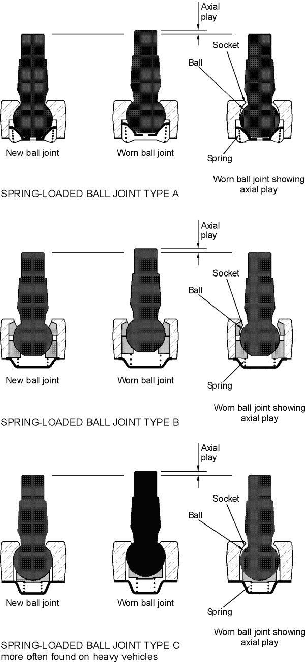
Figure 3-1-1. Examples of wear in spring-loaded ball joints
4 Jacking points for common suspension types
Reference
- General vehicles, 9-1 Steering and suspension systems
- Motorcycles, 9-1 Steering and suspension systems
- General trailers, 6-1 Steering and suspension systems.
Safety concern
Excessive wear in suspension ball joints can seriously affect the safe handling of the vehicle – if left unchecked, subsequent failure could cause a crash. Modern suspension systems employ multiple control arms, ball joints and compliance bushings, so it's important to check them all carefully during an inspection.
Inspection
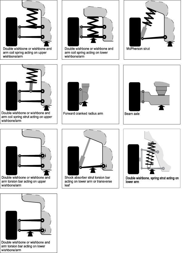
To help ensure ball joint wear is correctly detected, the images below show the jacking points for some common suspension types. They do not cover all suspension types or versions.
It's vital that the vehicle is jacked up correctly to avoid any damage. Depending on the type of suspension fitted to the vehicle, you may need to seek the manufacturer's guidance.
Page amended 1 October 2023 (see amendment details)
Page updated 7 November 2023 (see update details)
5 Webbing clamp seatbelts in class MA vehicles
Reference
Application
This bulletin applies to class MA vehicles fitted with a single- (R1) or dual- (R2) sensitive retractor seatbelt in a front outer seating position where that seatbelt has failed a WoF or CoF inspection.
This bulletin does not apply to vehicles:
- fitted with airbags as original equipment
- not listed in Table 5-1-1 (ie, where the fitting of webbing clamp seatbelts has not been approved by the vehicle manufacturer)
- that are required to comply with an approved frontal impact standard, ie vehicles with a GVM of 2500kg or less that were:
- manufactured on or after 1 March 1999
- first registered in New Zealand on or after 1 April 2002 that were less than 20 years old at the time of first registration in New Zealand
- with OE specification seatbelts that have features specifically designed to operate in conjunction with other parts of an integrated occupant protection system
- in which the fitting of a webbing clamp seatbelt would require modifications to the vehicle structure.
Safety concern
The seatbelts commonly referred to as ‘webbing clamp’ or ‘webbing grabber’ seatbelts have features that minimise uncontrolled webbing payout after the locking mechanism has been activated. This ensures that vehicle occupants are kept firmly in their seats in a crash. When installing a new seatbelt after the previous one has failed during a WoF or CoF inspection, a webbing clamp seatbelt is the safest option for many vehicles.
Inspection
A failed type R1 or R2 retractor seatbelt in a front outer seating position must be replaced with a webbing clamp seatbelt (see Figure 5-1-1) unless a webbing clamp seatbelt is not readily available (see Note 1), or the vehicle inspector has confirmation that the vehicle is one to which this bulletin does not apply.
Note 1
A seatbelt is considered not readily available where, eg, an automotive parts retailer normally able to supply webbing clamp seatbelts does not currently have the correct webbing clamp seatbelt in stock and cannot supply one within two working days by courier from the parts supplier. The vehicle operator must supply proof that the webbing clamp seatbelt was not readily available, eg an invoice from the seatbelt installer or retailer.
Vehicle inspectors must enter the inspection result as outlined in the flowchart in Figure 5-1-2.
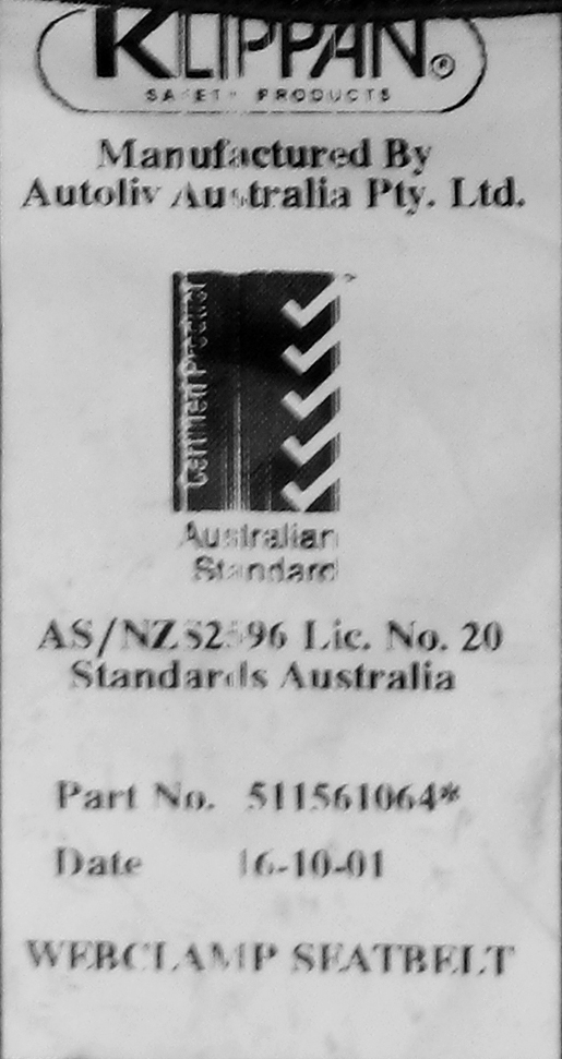
Figure 5-1-1. Example of a webbing clamp seatbelt label

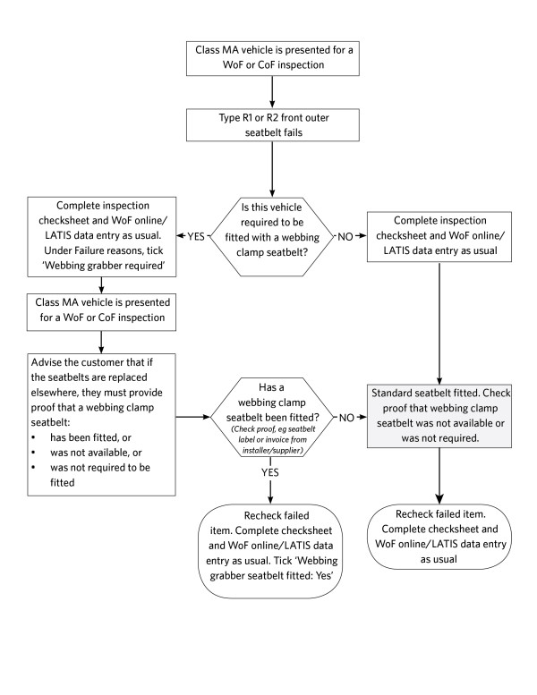
Figure 5-1-2. Webbing grabber seatbelt inspection process
Table 5-1-1. Vehicles generally approved for the fitment of webbing clamp seatbelts
|
Brand |
Model |
Variant |
Model Code |
Configuration |
Year |
|||||||||||||||||||||||||||||||||||||||||||||||||||||||||||||||||||||||||||||||||||||||||||||||||||||
|---|---|---|---|---|---|---|---|---|---|---|---|---|---|---|---|---|---|---|---|---|---|---|---|---|---|---|---|---|---|---|---|---|---|---|---|---|---|---|---|---|---|---|---|---|---|---|---|---|---|---|---|---|---|---|---|---|---|---|---|---|---|---|---|---|---|---|---|---|---|---|---|---|---|---|---|---|---|---|---|---|---|---|---|---|---|---|---|---|---|---|---|---|---|---|---|---|---|---|---|---|---|---|---|---|---|---|
|
Audi |
100 |
2.2L Quattro |
4 Door Sedan |
1985–1989 |
||||||||||||||||||||||||||||||||||||||||||||||||||||||||||||||||||||||||||||||||||||||||||||||||||||||
|
Audi |
100 |
Avant, Quattro |
4 Door S/Wagon |
1985–1991 |
||||||||||||||||||||||||||||||||||||||||||||||||||||||||||||||||||||||||||||||||||||||||||||||||||||||
|
Audi |
100 |
CD Avant |
4 Door S/Wagon |
1985–1991 |
||||||||||||||||||||||||||||||||||||||||||||||||||||||||||||||||||||||||||||||||||||||||||||||||||||||
|
Audi |
100 |
CD, CC, CS, E, EE |
WAUZZ |
4 Door Sedan |
1983–1991 |
|||||||||||||||||||||||||||||||||||||||||||||||||||||||||||||||||||||||||||||||||||||||||||||||||||||
|
Audi |
200 |
CD, CC, CS, E, EE |
WAUZZ |
4 Door Sedan |
1983–1991 |
|||||||||||||||||||||||||||||||||||||||||||||||||||||||||||||||||||||||||||||||||||||||||||||||||||||
|
BMW |
318 |
E30 |
4 Door Sedan |
1983–1991 |
||||||||||||||||||||||||||||||||||||||||||||||||||||||||||||||||||||||||||||||||||||||||||||||||||||||
|
BMW |
518 |
E34 |
4 Door Sedan |
1988–1992 |
||||||||||||||||||||||||||||||||||||||||||||||||||||||||||||||||||||||||||||||||||||||||||||||||||||||
|
BMW |
520 |
E34 |
4 Door S/Wagon |
1992–1996 |
||||||||||||||||||||||||||||||||||||||||||||||||||||||||||||||||||||||||||||||||||||||||||||||||||||||
|
BMW |
520 |
E34 |
4 Door Sedan |
1988–1999 |
||||||||||||||||||||||||||||||||||||||||||||||||||||||||||||||||||||||||||||||||||||||||||||||||||||||
|
BMW |
525 |
E34 |
4 Door S/Wagon |
1992–1996 |
||||||||||||||||||||||||||||||||||||||||||||||||||||||||||||||||||||||||||||||||||||||||||||||||||||||
|
BMW |
525 |
E34 |
4 Door Sedan |
1988–1999 |
||||||||||||||||||||||||||||||||||||||||||||||||||||||||||||||||||||||||||||||||||||||||||||||||||||||
|
BMW |
535 |
E34 |
4 Door Sedan |
1988–1992 |
||||||||||||||||||||||||||||||||||||||||||||||||||||||||||||||||||||||||||||||||||||||||||||||||||||||
|
BMW |
540 |
E34 |
4 Door S/Wagon |
1992–1996 |
||||||||||||||||||||||||||||||||||||||||||||||||||||||||||||||||||||||||||||||||||||||||||||||||||||||
|
BMW |
540 |
E34 |
4 Door Sedan |
1993–1999 |
||||||||||||||||||||||||||||||||||||||||||||||||||||||||||||||||||||||||||||||||||||||||||||||||||||||
|
BMW |
730 |
E32 |
4 Door Sedan |
1985–1994 |
||||||||||||||||||||||||||||||||||||||||||||||||||||||||||||||||||||||||||||||||||||||||||||||||||||||
|
BMW |
735 |
E32 |
4 Door Sedan |
1985–1994 |
||||||||||||||||||||||||||||||||||||||||||||||||||||||||||||||||||||||||||||||||||||||||||||||||||||||
|
BMW |
740 |
E32 |
4 Door Sedan |
1985–1994 |
||||||||||||||||||||||||||||||||||||||||||||||||||||||||||||||||||||||||||||||||||||||||||||||||||||||
|
BMW |
750 |
E32 |
4 Door Sedan |
1988–1994 |
||||||||||||||||||||||||||||||||||||||||||||||||||||||||||||||||||||||||||||||||||||||||||||||||||||||
|
Daihatsu |
Charade |
2 Door Hatch |
1983–1987 |
|||||||||||||||||||||||||||||||||||||||||||||||||||||||||||||||||||||||||||||||||||||||||||||||||||||||
|
Daihatsu |
Charade |
CS |
G11 |
4 Door Hatch |
1983–1988 |
|||||||||||||||||||||||||||||||||||||||||||||||||||||||||||||||||||||||||||||||||||||||||||||||||||||
|
Daihatsu |
Charade |
CS, CX Turbo, TS |
E-G112S |
2 Door Hatch |
1987–1993 |
|||||||||||||||||||||||||||||||||||||||||||||||||||||||||||||||||||||||||||||||||||||||||||||||||||||
|
Daihatsu |
Charade |
CS, CX Turbo, TS |
E-G100 |
2 Door Hatch |
1987–1993 |
|||||||||||||||||||||||||||||||||||||||||||||||||||||||||||||||||||||||||||||||||||||||||||||||||||||
|
Daihatsu |
Charade |
CS, CX Turbo, TS |
E-G102 |
2 Door Hatch |
1987–1993 |
|||||||||||||||||||||||||||||||||||||||||||||||||||||||||||||||||||||||||||||||||||||||||||||||||||||
|
Daihatsu |
Charade |
CX, TL, CS, Turbo |
E-G100 |
4 Door Sedan |
1983–1987 |
|||||||||||||||||||||||||||||||||||||||||||||||||||||||||||||||||||||||||||||||||||||||||||||||||||||
|
Daihatsu |
Charade |
LS, LX, EX |
E-G200 |
4 Door Hatch |
1993–1998 |
|||||||||||||||||||||||||||||||||||||||||||||||||||||||||||||||||||||||||||||||||||||||||||||||||||||
|
Daihatsu |
Charade |
LS, LX, EX |
E-G203 |
4 Door Hatch |
1993–1998 |
|||||||||||||||||||||||||||||||||||||||||||||||||||||||||||||||||||||||||||||||||||||||||||||||||||||
|
Daihatsu |
Charade |
LS, LX, EX |
E-G213 |
4 Door Hatch |
1993–1998 |
|||||||||||||||||||||||||||||||||||||||||||||||||||||||||||||||||||||||||||||||||||||||||||||||||||||
|
Daihatsu |
Charade |
SEI |
E-G203S |
4 Door Sedan |
1995–1997 |
|||||||||||||||||||||||||||||||||||||||||||||||||||||||||||||||||||||||||||||||||||||||||||||||||||||
|
Daihatsu |
Charade |
SEI |
E-G200S |
4 Door Sedan |
1995–1997 |
|||||||||||||||||||||||||||||||||||||||||||||||||||||||||||||||||||||||||||||||||||||||||||||||||||||
|
Daihatsu |
Charade |
TS (white only) |
2 Door Hatch |
1991–1991 |
||||||||||||||||||||||||||||||||||||||||||||||||||||||||||||||||||||||||||||||||||||||||||||||||||||||
|
Daihatsu |
Mira |
850 4WD |
L201 |
2 Door Sedan |
1990–1993 |
|||||||||||||||||||||||||||||||||||||||||||||||||||||||||||||||||||||||||||||||||||||||||||||||||||||
|
Daihatsu |
Mira |
LS, LX |
L201 |
4 Door Sedan |
1990–1998 |
|||||||||||||||||||||||||||||||||||||||||||||||||||||||||||||||||||||||||||||||||||||||||||||||||||||
|
Daihatsu |
Mira |
LS, LX |
L500 |
4 Door Sedan |
1990–1998 |
|||||||||||||||||||||||||||||||||||||||||||||||||||||||||||||||||||||||||||||||||||||||||||||||||||||
|
Daihatsu |
Mira |
LS |
L8ORS |
4 Door Hatch |
1986–1990 |
|||||||||||||||||||||||||||||||||||||||||||||||||||||||||||||||||||||||||||||||||||||||||||||||||||||
|
Fiat |
Punto |
55 SX |
ZFA176 |
4 Door Liftback |
1994–1995 |
|||||||||||||||||||||||||||||||||||||||||||||||||||||||||||||||||||||||||||||||||||||||||||||||||||||
|
Fiat |
Punto |
55, GT |
ZFA176 |
2 Door Hatch |
1994–1995 |
|||||||||||||||||||||||||||||||||||||||||||||||||||||||||||||||||||||||||||||||||||||||||||||||||||||
|
Ford |
Autozam |
4 Door Sedan |
1991–1997 |
|||||||||||||||||||||||||||||||||||||||||||||||||||||||||||||||||||||||||||||||||||||||||||||||||||||||
|
Ford |
Autozam |
AZ-3 |
2 Door Coupe |
1991–1997 |
||||||||||||||||||||||||||||||||||||||||||||||||||||||||||||||||||||||||||||||||||||||||||||||||||||||
|
Ford |
Capri |
XRS, Barchetta |
2 Door Convert |
1990–1994 |
||||||||||||||||||||||||||||||||||||||||||||||||||||||||||||||||||||||||||||||||||||||||||||||||||||||
|
Ford |
Clef |
4 Door Sedan |
1991–1997 |
|||||||||||||||||||||||||||||||||||||||||||||||||||||||||||||||||||||||||||||||||||||||||||||||||||||||
|
Ford |
Fairlane |
EA |
4 Door Sedan |
1988–1993 |
||||||||||||||||||||||||||||||||||||||||||||||||||||||||||||||||||||||||||||||||||||||||||||||||||||||
|
Ford |
Falcon |
S |
EF |
4 Door S/Wagon |
1989–1993 |
|||||||||||||||||||||||||||||||||||||||||||||||||||||||||||||||||||||||||||||||||||||||||||||||||||||
|
Ford |
Falcon |
S |
EB |
4 Door Sedan |
1989–1993 |
|||||||||||||||||||||||||||||||||||||||||||||||||||||||||||||||||||||||||||||||||||||||||||||||||||||
|
Ford |
Falcon |
S |
EB |
4 Door S/Wagon |
1989–1993 |
|||||||||||||||||||||||||||||||||||||||||||||||||||||||||||||||||||||||||||||||||||||||||||||||||||||
|
Ford |
Falcon |
S |
ED |
4 Door S/Wagon |
1989–1993 |
|||||||||||||||||||||||||||||||||||||||||||||||||||||||||||||||||||||||||||||||||||||||||||||||||||||
|
Ford |
Falcon |
S |
ED |
4 Door Sedan |
1989–1993 |
|||||||||||||||||||||||||||||||||||||||||||||||||||||||||||||||||||||||||||||||||||||||||||||||||||||
|
Ford |
Falcon |
S |
EF |
4 Door Sedan |
1989–1993 |
|||||||||||||||||||||||||||||||||||||||||||||||||||||||||||||||||||||||||||||||||||||||||||||||||||||
|
Ford |
Falcon |
EA |
4 Door S/Wagon |
1988–1990 |
||||||||||||||||||||||||||||||||||||||||||||||||||||||||||||||||||||||||||||||||||||||||||||||||||||||
|
Ford |
Falcon |
XG |
4 Door S/Wagon |
1985–1993 |
||||||||||||||||||||||||||||||||||||||||||||||||||||||||||||||||||||||||||||||||||||||||||||||||||||||
|
Ford |
Falcon |
XG |
4 Door Sedan |
1985–1993 |
||||||||||||||||||||||||||||||||||||||||||||||||||||||||||||||||||||||||||||||||||||||||||||||||||||||
|
Ford |
Falcon |
EA |
4 Door Sedan |
1988–1990 |
||||||||||||||||||||||||||||||||||||||||||||||||||||||||||||||||||||||||||||||||||||||||||||||||||||||
|
Ford |
Festiva |
S, Trio, GLXi |
E-D23 |
2 Door Hatch |
1993–2001 |
|||||||||||||||||||||||||||||||||||||||||||||||||||||||||||||||||||||||||||||||||||||||||||||||||||||
|
Ford |
Festiva |
S, Trio, GLXi |
E-D25PF |
2 Door Hatch |
1993–2001 |
|||||||||||||||||||||||||||||||||||||||||||||||||||||||||||||||||||||||||||||||||||||||||||||||||||||
|
Ford |
Festiva |
Trio, GLXi |
DAFP3 |
2 Door Hatch |
1995–1998 |
|||||||||||||||||||||||||||||||||||||||||||||||||||||||||||||||||||||||||||||||||||||||||||||||||||||
|
Ford |
Festiva |
Trio, GLXi |
DAFP3 |
4 Door Hatch |
1995–1998 |
|||||||||||||||||||||||||||||||||||||||||||||||||||||||||||||||||||||||||||||||||||||||||||||||||||||
|
Ford |
Festiva |
E-DA3PF |
4 Door Hatch |
1985–1993 |
||||||||||||||||||||||||||||||||||||||||||||||||||||||||||||||||||||||||||||||||||||||||||||||||||||||
|
Ford |
Festiva |
E-DA3PF |
2 Door Hatch |
1985–1993 |
||||||||||||||||||||||||||||||||||||||||||||||||||||||||||||||||||||||||||||||||||||||||||||||||||||||
|
Ford |
Laser |
1.3C |
LO3 |
2 Door Hatch |
1987–1990 |
|||||||||||||||||||||||||||||||||||||||||||||||||||||||||||||||||||||||||||||||||||||||||||||||||||||
|
Ford |
Laser |
1.5 Sport |
2 Door Hatch |
1983–1987 |
||||||||||||||||||||||||||||||||||||||||||||||||||||||||||||||||||||||||||||||||||||||||||||||||||||||
|
Ford |
Laser |
GL |
L04 |
4 Door Liftback |
1992–1994 |
|||||||||||||||||||||||||||||||||||||||||||||||||||||||||||||||||||||||||||||||||||||||||||||||||||||
|
Ford |
Laser |
L |
L05 |
2 Door Hatch |
1986 |
|||||||||||||||||||||||||||||||||||||||||||||||||||||||||||||||||||||||||||||||||||||||||||||||||||||
|
Ford |
Laser |
Sport |
2 Door Hatch |
1981–1984 |
||||||||||||||||||||||||||||||||||||||||||||||||||||||||||||||||||||||||||||||||||||||||||||||||||||||
|
Ford |
Laser |
TX3 |
KF |
2 Door Hatch |
1990–1994 |
|||||||||||||||||||||||||||||||||||||||||||||||||||||||||||||||||||||||||||||||||||||||||||||||||||||
|
Ford |
Laser |
BF5PF |
4 Door S/Wagon |
1990–1994 |
||||||||||||||||||||||||||||||||||||||||||||||||||||||||||||||||||||||||||||||||||||||||||||||||||||||
|
Ford |
Laser |
BG8PF |
4 Door Sedan |
1990–1995 |
||||||||||||||||||||||||||||||||||||||||||||||||||||||||||||||||||||||||||||||||||||||||||||||||||||||
|
Ford |
Laser |
KH |
4 Door Sedan |
1990–1995 |
||||||||||||||||||||||||||||||||||||||||||||||||||||||||||||||||||||||||||||||||||||||||||||||||||||||
|
Ford |
Laser |
BG6PF |
4 Door Sedan |
1992–1994 |
||||||||||||||||||||||||||||||||||||||||||||||||||||||||||||||||||||||||||||||||||||||||||||||||||||||
|
Ford |
Laser |
KF |
4 Door Sedan |
1990–1995 |
||||||||||||||||||||||||||||||||||||||||||||||||||||||||||||||||||||||||||||||||||||||||||||||||||||||
|
Ford |
Laser |
BG5PF |
4 Door Sedan |
1990–1993 |
||||||||||||||||||||||||||||||||||||||||||||||||||||||||||||||||||||||||||||||||||||||||||||||||||||||
|
Ford |
Laser |
2 Door Hatch |
1987–1989 |
|||||||||||||||||||||||||||||||||||||||||||||||||||||||||||||||||||||||||||||||||||||||||||||||||||||||
|
Ford |
Ltd |
XE |
4 Door Sedan |
1981–1988 |
||||||||||||||||||||||||||||||||||||||||||||||||||||||||||||||||||||||||||||||||||||||||||||||||||||||
|
Ford |
Ltd |
XF |
4 Door Sedan |
1981–1988 |
||||||||||||||||||||||||||||||||||||||||||||||||||||||||||||||||||||||||||||||||||||||||||||||||||||||
|
Ford |
Ltd |
EB |
4 Door Sedan |
1991–1993 |
||||||||||||||||||||||||||||||||||||||||||||||||||||||||||||||||||||||||||||||||||||||||||||||||||||||
|
Ford |
Ltd |
EA |
4 Door Sedan |
1988–1993 |
||||||||||||||||||||||||||||||||||||||||||||||||||||||||||||||||||||||||||||||||||||||||||||||||||||||
|
Ford |
Mondeo |
WFOX |
4 Door Sedan |
1993–1994 |
||||||||||||||||||||||||||||||||||||||||||||||||||||||||||||||||||||||||||||||||||||||||||||||||||||||
|
Ford |
Mondeo |
WFOX |
4 Door S/Wagon |
1993–1994 |
||||||||||||||||||||||||||||||||||||||||||||||||||||||||||||||||||||||||||||||||||||||||||||||||||||||
|
Ford |
Sierra |
4 Door Sedan |
1985–1992 |
|||||||||||||||||||||||||||||||||||||||||||||||||||||||||||||||||||||||||||||||||||||||||||||||||||||||
|
Ford |
Sierra |
Cosworth |
S15/88B |
4 Door Liftback |
1988–1992 |
|||||||||||||||||||||||||||||||||||||||||||||||||||||||||||||||||||||||||||||||||||||||||||||||||||||
|
Ford |
Sierra |
GLX |
S15/90BB |
4 Door S/Wagon |
1988–1992 |
|||||||||||||||||||||||||||||||||||||||||||||||||||||||||||||||||||||||||||||||||||||||||||||||||||||
|
Ford |
Sierra |
XR 4X4 |
S15/85BB |
4 Door Liftback |
1985–1992 |
|||||||||||||||||||||||||||||||||||||||||||||||||||||||||||||||||||||||||||||||||||||||||||||||||||||
|
Ford |
Sierra |
4 Door S/Wagon |
1984–1988 |
|||||||||||||||||||||||||||||||||||||||||||||||||||||||||||||||||||||||||||||||||||||||||||||||||||||||
|
Ford |
Taurus |
4 Door Sedan |
1992–1994 |
|||||||||||||||||||||||||||||||||||||||||||||||||||||||||||||||||||||||||||||||||||||||||||||||||||||||
|
Ford |
Telstar |
GL |
E-GEFPF |
4 Door S/Wagon |
1993–1997 |
|||||||||||||||||||||||||||||||||||||||||||||||||||||||||||||||||||||||||||||||||||||||||||||||||||||
|
Ford |
Telstar |
GLi, GLEi, Ghia |
C-HIAVE |
4 Door Sedan |
1992–1997 |
|||||||||||||||||||||||||||||||||||||||||||||||||||||||||||||||||||||||||||||||||||||||||||||||||||||
|
Ford |
Telstar |
V6 XRi |
GEEPF, T77 |
6 Inspection requirements for temporary vehicle importsApplicationThis bulletin specifies the in-service inspection requirements for vehicles that have been imported temporarily from overseas. A temporary import vehicle is brought into the country by a resident of another country, usually for a maximum period of 18 months, while the vehicle remains registered in its country of origin. The vehicle must be exported from New Zealand within that period. Inspecting a temporary import vehicle for WoF or CoFBefore inspecting a temporary import vehicle for WoF or CoF, the vehicle inspector must check that the following requirements have been met: 1. The vehicle must have the overseas registration plates attached. 2. The registration plate number must be the same as on the licence label. Note Where the plate number has more than six digits, only the first six digits of the plate number are on the label. Where those digits already exist in the system, the six digits on the label will start with a ‘V’, followed by the first five digits of the plate number. 3. The label correctly describes the vehicle to which the plates are attached. 4. The licence label must be current or have expired no more than 12 months ago. 5. The label indicates that the vehicle has been ‘first registered’ in New Zealand less than 18 months ago. If the above requirements are not met, or the vehicle inspector finds that the vehicle is not on the system, a WoF or CoF must not be issued. Please refer the vehicle to the nearest TSD agent. Vehicle inspection requirementsTemporary import vehicles do not require entry or specialist certification, but are required to comply with the basic safety requirements listed in the provisions of the Geneva Convention on Road Traffic. These provisions are outlined below. For WoF/CoF inspection purposes, they apply to all temporary import vehicles, including cars, trucks and trailers, but not including mopeds and other vehicles that don’t require a WoF or CoF in New Zealand. The vehicle inspector may use the main parts of the VIRM for further guidance. Note Temporarily imported vehicles do not have to meet requirements for modification. Therefore, low volume vehicle (LVV) or heavy vehicle specialist (HVS) certification is not required. However, if a vehicle inspector feels that a vehicle is unsafe to operate, he/she may seek advice from a low volume vehicle or heavy vehicle specialist certifier. See Table 6-1-1: Group M and N vehicles, Table 6-1-2: Group L vehicles and Table 6-1-3: Trailers.
Table 6-1-1. Group M and N vehicles
Table 6-1-2. Group L vehicles
Table 6-1-3. Trailers
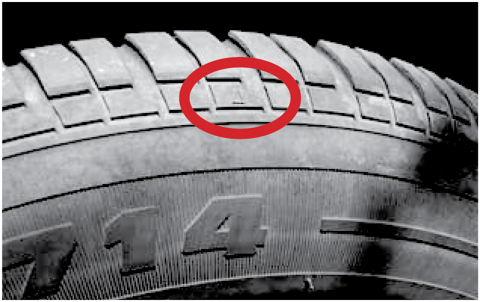
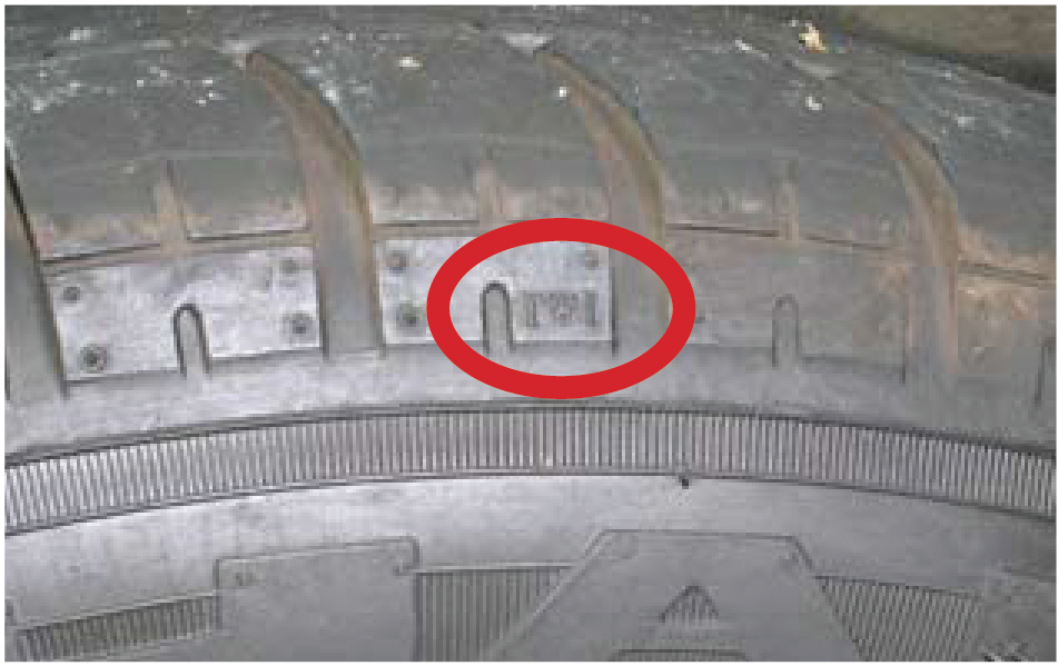
7 Guidance for vehicle inspectors when checking tyre tread depthReference
Land Transport Rule: Tyres and Wheels 2001 has been amended to include new tyre tread depth requirements. These requirements became law on 1 November 2007. They take into account new tyre tread designs and allow for more consistent checking of tread depth during vehicle inspections. Below is some guidance to help vehicle inspectors measure tyre tread depth to the new requirements for different kinds of tread patterns. What is the new requirement for tyre tread depth?The rule now states that a tyre must have a tread pattern depth of at least 1.5mm (excluding any tie-bar or tread depth indicator strip) within all principal grooves that contain moulded tread depth indicators and around the whole circumference of the tyre. Virtually all tyres have moulded tread-depth indicators. However, a small number of tyres, such as some retreaded or vintage tyres, may not have moulded tread-depth indicators. For these, the NZTA has retained the old requirement of at least 1.5mm tread depth across ¾ of the tread width and around the whole circumference of the tyre. What are principal grooves and tread depth indicators, and how do I find these?Principal grooves are the wide grooves in the tyre tread which have the tread-depth indicators located inside them. Any other grooves are secondary grooves which may wear out during the service life of the tyre. Tread-depth indicators (also known as tread wear indicators or TWIs) are the projections within the principal grooves that let you know how far the tread has worn and are usually about 1.6-2.2mm thick. If you find it difficult to find tread-depth indicators, just look along the side wall for a small ‘ Where do I measure the tread depth?The tread depth is measured in the principal grooves that contain the tread-depth indicators. However, there are tread patterns where the principal grooves cover different widths of tyre tread. This means that in order to pass a WoF or CoF some tyres must have 1.5mm tread depth across a greater tread width than other tyres. This is especially the case for tyres that have lateral grooves (those that end at the tyre edges), as shown in Example 1 of Figure 7-1-3. Vehicle inspectors may disregard the outer end of a lateral groove where it normally tapers off over the shoulder. Note that the tread is only that part of the tyre that is in contact with the ground. Figure 7-1-3 shows different tread patterns with tread-depth indicators (and therefore principal grooves) and the approximate measuring width marked. Figure 7-1-1. The '
|

|
BMW |
|---|
|
IMPORTANT INFORMATION – READ BEFORE TESTING THE BRAKES:
Testing the electro-mechanical parking brake (EMF) found on most BMW vehiclesYou can recognise EMF by the existence of a pull or push electrical button to apply the hand brake rather than a hand brake lever. To test the EMF parking brake, you must carry out the following procedure:
Testing the service brakes on all BMW X-drive 4x4 vehiclesAs a precaution, treat all BMW 4x4 vehicles as X-drive vehicles. To test the service brakes on a roller brake machine (which must have 4WD mode), carry out the following procedure:
|
Page added 14 October 2013 (see amendment details).
11 Electronic stability control identification
Identification of Electronic Stability Control (ESC)
The following evidence is acceptable proof that the vehicle is fitted with an ESC system:
- The presence and correct operation of appropriate ESC tell-tale indicators on the vehicle’s dashboard
- A tell-tale indicator like the symbol below refers to an ESC system:

- A tell-tale indicator on the vehicle’s dashboard comprising one of the following acronyms:
AUDI | ESP (Electronic Stabilization Program) |
BMW | DSC (Dynamic Stability Control)
|
| DTC (Dynamic Traction Control) Note: If a BMW has DTC displayed the vehicle can be accepted as containing an ESC system. The underlying technology to DTC includes DSC - which is an ESC system) | |
CRYSLER | ESP (Electronic Stability Program) |
DAIHATSU | DVS (Daihatsu Vehicle Stability control system) |
FORD | ESP (Electronic Stability Program) |
DSC (Dynamic Stability Control) | |
GM | PSC (Precision Control System) |
| HOLDEN | ESC (Electronic Stability Control) |
HONDA | VSA (Vehicle Stability Assist) |
JAGUAR | DSC (Dynamic Stability Control) |
LANDROVER | DSC (Dynamic Stability Control) |
LEXUS | VSC (Vehicle Stability Control) |
VDIM (Vehicle Dynamics Integration Management) | |
| MASERATI | MSP (Maserati Stability Program) |
MAZDA | DSC (Dynamic Stability Control) |
MERCEDES-BENZ | ESP (Electronic Stability Program) |
| MINI | DSC (Dynamic Stability Control) |
MITSUBISHI | ASC (Active Stability Control) |
ASTC (Active Stability and Traction Control) | |
NISSAN | VDC (Vehicle Dynamics Control) |
| PORSCHE | PSM (Porsche Stability Management) |
SUBARU | VDC (Vehicle Dynamics Control) |
SUZUKI | ESP (Electronic Stability Program) |
TOYOTA | VDIM (Vehicle Dynamics Integration Management) |
VSC (Vehicle Stability Control) | |
VOLVO | DSTC (Dynamic Stability and Traction Control) |
VOLKSWAGEN | ESP (Electronic Stabilization Program) |
The above list is not exhaustive, other manufacturer-specific symbols or acronyms may also be acceptable if the certifier is satisfied that the lamp refers to an ESC system.
However, a tell-tale indicator with the letters 'TC' or 'Traction Control' is not an indication of ESC fitment and cannot be accepted as such. The Transport Agency is aware of a letter provided by a Land Rover dealer erroneously stating that vehicles with 'TC' tell-tales are fitted with a form of ESC. This letter cannot be accepted as evidence of ESC fitment.
Identification of an ESC fault
An ESC fault is normally identified by the tell-tale indicator lamp not extinguishing at the conclusion of the self-check process initiated when the vehicle’s ignition is switched on.
Page added 1 March 2016 (see amendment details)
Page updated 25 February 2021 (see details)
12 Used imported vehicles from Japan – disconnected airbags at WoF inspection
March 2020 | Version 4
Version history
|
Version |
Date |
Details |
|---|---|---|
|
1 |
14 October 2016 |
Outlines how to identify vehicles affected by the recall and what to do. |
|
2 |
2 November 2016 |
Mazda information is now also available. |
|
3 |
28 November 2016 |
Replacement of email notification process with web-based notification process through http://rightcar.govt.nz/recalls/wof (link inactive). |
| 4 | 11 March 2020 | Technical bulletin rescinded. Vehicles with disconnected airbags should be failed in line with section 7-6 Frontal impact airbags reason for rejection 7. Airbags must be reconnected and working to issue the WoF. The Transport Agency does not need to be specifically notified. |
Page updated 11 March 2020
13 Acceptable overseas proof of modification
The table below lists the overseas certifications that are accepted in addition to New Zealand's low volume vehicle certification system.
| Acceptable overseas certifications | Specific evidence |
|---|---|
|
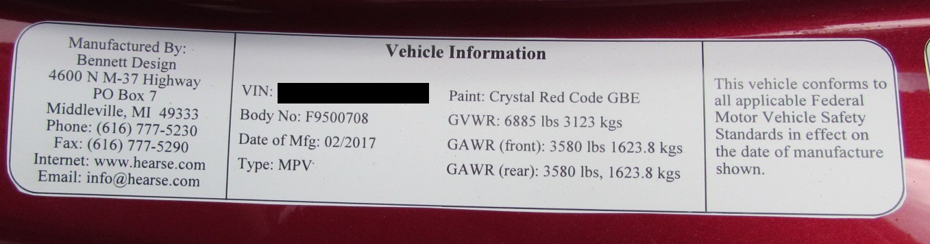
Australia ADR SSM: Australian Motor Vehicle Certification Board Second Stage of Manufacture | The plate/label is silver in colour. If the word ‘nonstandard’ or the phrase 'low volume’ appears on the plate/label the certification cannot be accepted, refer to a specialist certifier. See Figure 13-1-1 for a sample plate/label. |
| Europe ECWVTA: European Community Whole Vehicle Type Approval |
Note 1 A motorhome may have final stage approval to 2001/116/EC provided it was approved to 2007/46/EC or 2018/858/EC at an earlier approval stage (ie there is a base or second stage approval label listing 2007/46/EC in addition to the 2001/116/EC final stage label). |
| United States FMVSS: Federal Motor Vehicle Safety Standards |
Motorhomes, hearses and limousines with an FMVSS approval plate. See Figure 13-1-4 for a sample FMVSS approval plate. Note: Conversion vans (aka day vans) are not motorhomes as they are not a dwelling place. The Transport Agency requires these vehicles to be LVV certified. |
Figure 13-1-1. ADR SSM plate/label
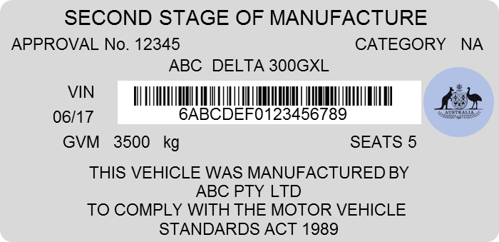
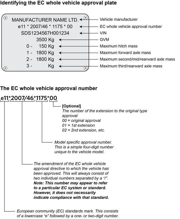
Figure 13-1-2. Sample European Community Whole Vehicle Type Approval - ECWVTA
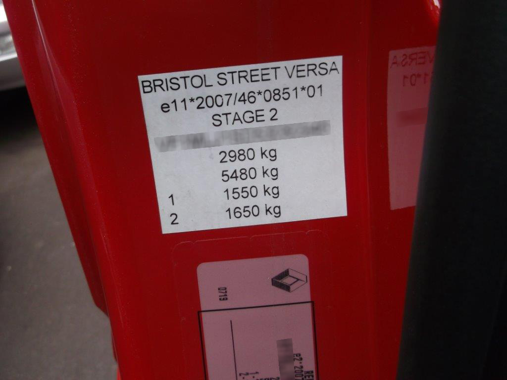
Figure 13-1-3. Example of Stufe 2
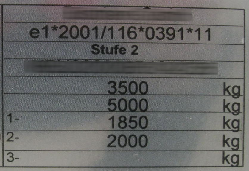
Figure 13-1-4. Sample FMVSS approval plate
Page amended 1 April 2021 (see amendment details).
14 LED light bars
A number of automotive LED light bars are readily available on the market and are being fitted to vehicles. Light bars are long lamps that consist of an array of LEDs, and that project a beam of light. These are generally intended to be fitted as a single lamp to the front centre of a vehicle.
These light bars typically resemble the following: 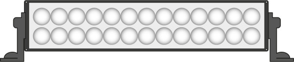
and
![]()
Light bars can be fitted as either headlamps or work lamps, but there are some very specific requirements around each type of fitting and use.
Light bars fitted as headlamps
- On cars and trucks, all headlamps must be fitted as a pair (eg not a single centred headlamp). This means that a centre-mounted single light bar cannot be considered a headlamp.
- Cars and trucks must be fitted with only one pair of dipped-beam headlamps and up to a maximum of two pairs of main-beam headlamps. Since vehicles come with an OEM dipped-beam headlamp, a light bar cannot be added for dipped-beam use (because a second pair is not allowed).
- On mopeds and motorcycles, headlamps can be fitted singly or in pairs, to a maximum of two dipped-beam headlamps and two main-beam headlamps.
- The headlamps cannot dazzle, confuse, or distract so as to endanger the safety of other road users.
- The centre of the beam pattern must be pointed horizontally or down (not upwards) and to the centre or left (not to the right).
- The main-beam headlamps must still be able to be dipped or extinguished from the driver’s seating position.
- All headlamps must meet an approved safety standard unless fitted to older vehicles (before 1992 for class MA and NA, before 1996 for others (excluding group L, which are before 2006)).
Note: because many light bars on the New Zealand market do not comply with approved standards for headlamps, they cannot be fitted to a vehicle as headlamps.
Light bars fitted as work lamps
- A vehicle, other than a moped, may be fitted with one or more work lamps, which are defined as follows:
- Work lamp means a high intensity lamp, which is not necessary for the operation of the vehicle but is designed to illuminate a work area or scene; and includes:
(a) a scene lamp; and
(b) a spot lamp; and
(c) an alley lamp.
- Work lamp means a high intensity lamp, which is not necessary for the operation of the vehicle but is designed to illuminate a work area or scene; and includes:
- A work lamp isn’t for normal on-road driving.
- Work lamps may only be used when the vehicle to which they’re fitted is stationary or travelling slowly; and to illuminate a work area or scene.
- A work lamp must not be wired into the head lamps and must be switched to operate independently of other lighting equipment.
Note: a work lamp:
- cannot be fitted to a moped
- doesn’t need to meet a lighting standard (as it is for off-road use only)
How to treat light bars at WoF/CoF when fitted as headlamps
Note: because many light bars on the New Zealand market do not comply with approved standards for headlamps, they cannot be fitted to a vehicle as headlamps.
The first step is to determine if the lamp complies with an approved standard. Standards compliant lamps on sale in New Zealand should carry standards markings on the lens.
- European markings will consist of a circle containing a capital “E” followed by a number, or a rectangle containing a lower case “e” followed by a number (it does not matter what the number is)
- American markings will be the letters DOT, for example:


If one of these markings is found, the lamp can be accepted as standards compliant (Note: The Transport Agency is not aware of any of these lamps that have Japanese standards compliance).
If there are no markings on the lamp, it is likely to be non-compliant. The Transport Agency is not aware of any compliant light bars without standards markings at this time, but will update this bulletin if any are found on the market.
How to treat light bars at WoF/CoF when fitted as work lamps
A non-standards compliant light bar, or a standards compliant light bar that is fitted as a single lamp might be classified as a work lamp if it were switched independently of all other lighting equipment.
In this case, the owner/operator of the vehicle should be advised that it is illegal to use the lamp for normal on-road driving.
If a non-compliant light bar is fitted, and it does not meet the criteria for being considered a work lamp, it must be failed a WoF/CoF.
Page added 1 November 2018 (see amendment details).
15 Identifying compliant hitches and brake systems
Imported trailers with whole vehicle type approval
A trailer that has European whole vehicle type approval will have brakes compliant with UN/ECE Regulation 13. These trailers are identified by a plate very similar to the following:
Trailers fitted with a UN/ECE Regulation 13 braking system
These trailers are usually built in New Zealand and fitted with an imported braking system. An approved braking system can be identified by the features and markings detailed below. If these features and markings are not present the owner must be able to present documentation that reasonably proves the braking system is compliant with UN/ECE Reg.13 and Reg.55.
Compliant hitch
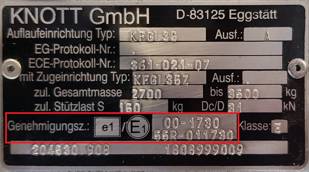
- A compliant hitch will be fitted with a plate like the one above that indicates it is compliant to Reg. 55 as per the red highlighted section in the image.
Compliant brake system
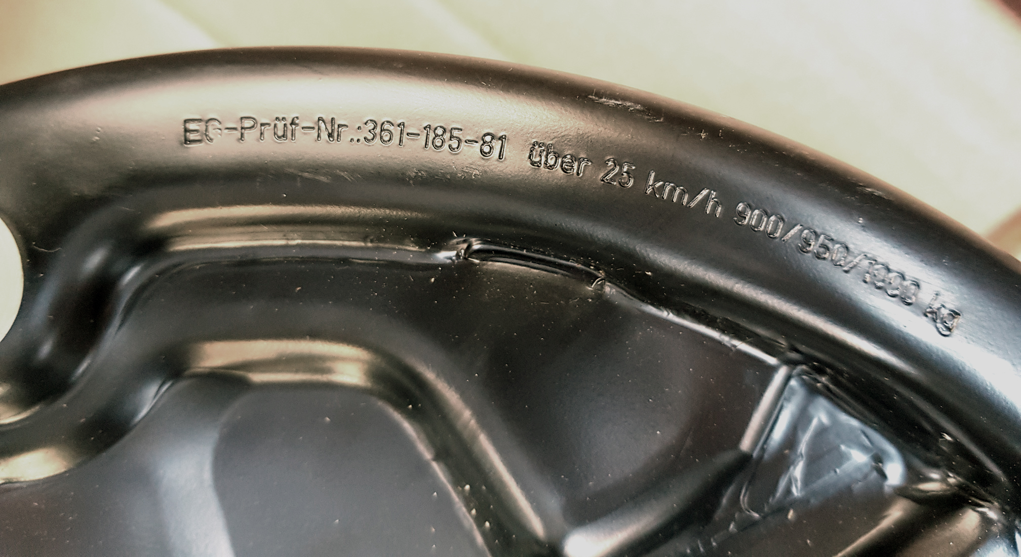
- compliant brake system will require a brake acting on each wheel of every axle (ie two individual brakes on a single axle, four on a twin axle, and six on a tri axle). The back of each brake drum will have a test number marking like that shown above.
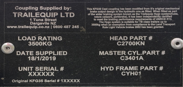
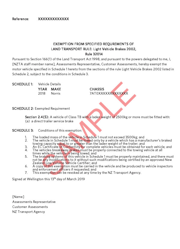
Trailers without a UN/ECE approved brake system
Trailers presented without a European approved braking system, as per the two sections above, must be presented with an exemption letter issued by the Transport Agency. An example of this may be seen below. These trailers are usually built in New Zealand and are usually fitted with a brake system manufactured in New Zealand. Some of these trailers will be fitted with a plate like the one shown below. All these trailers must have a VIN/chassis that matches that shown on the exemption letter.
Sample exemption letter
Page added 1 June 2019 (see amendment details)
Page updated 1 May 2020 (see details)
16 Seatbelt repair and re-webbing
Requirements for seatbelt repair
A seatbelt may only be legally repaired by the seatbelt manufacturer or their authorised agent.
There are currently no mass-manufacturers or agents repairing seatbelts in New Zealand.
Re-webbing a seatbelt is considered to be a repair.
NZTA has provided an exemption to the following companies to re-web seatbelts manufactured by other seatbelt providers:
- APV Australia
- Autosafe Ltd, Christchurch
- Belt Tech NZ Ltd, Wellington
- Seatbelts NZ Ltd
- Seatbelt Manufacturers NZ Ltd.
Further companies will be added to this list as they are approved.
Identifying compliant re-webbed seatbelts
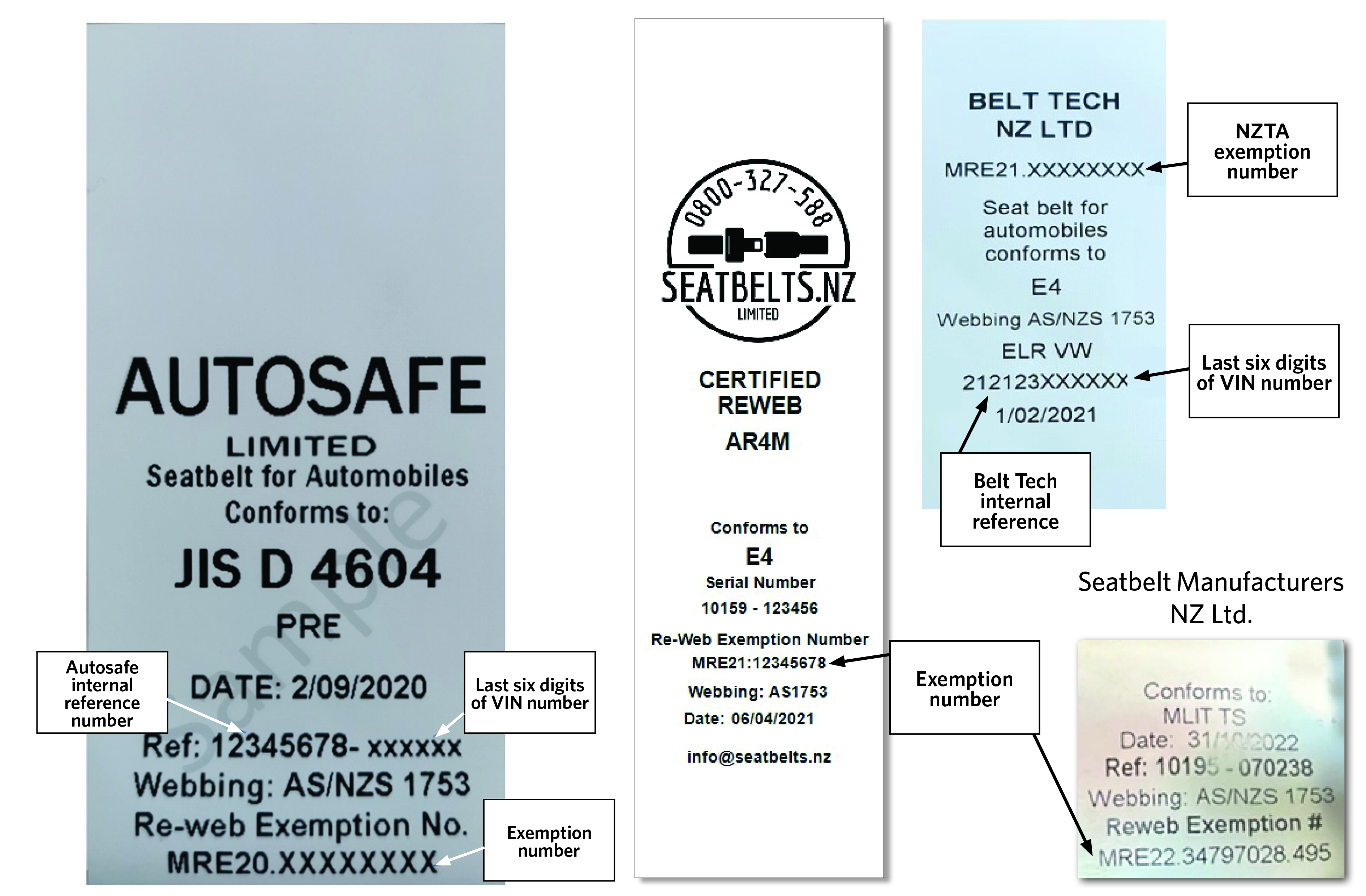
To be compliant a re-webbed seatbelt must have a label with an exemption number (Figure 16-1-1) and either an exemption letter (paper copy in the vehicle) or be confirmed on the websites below.
- For Autosafe use the 'Look Up REGO' function found on the Autosafe website
- For Seatbelts NZ Ltd use the check vehicle function on the Seatbelts NZ Ltd website
- For Belt Tech NZ Ltd enter the last six digits of the vehicle's VIN to look up the vehicle on the Belt Tech NZ Ltd website
- For Seatbelt Manufacturers NZ Ltd an exemption letter is required
- APV are not actively re-webbing seatbelts but these must also have an exemption letter.
Identifying non-compliant re-webbed seatbelts
Seatbelts that are re-webbed without an exemption from NZTA may not be accepted for a WoF or CoF.
Most non-compliant re-webbed seatbelts are done in a way to hide that they are re-webbed. The following indicators are the best way to identify a non-compliant re-webbed seatbelt:
- incorrectly fitted hardware such as buckles on webbing that looks new
- new webbing, or webbing that looks newer than the other seatbelts in the vehicle, with the same compliance tags as the original seat belts
- the same identification tags as the original belts with a different stitch pattern
- a compliance label that is different to the other seatbelts that is not from a typical manufacturer
- no compliance labels fitted on new webbing or a new seatbelt.
Getting a seatbelt re-webbed
If you are trying to help a vehicle owner to get their seatbelt re-webbed it is important that you only use an approved company. NZTA is aware that there are other companies who re-web seatbelts - this is an illegal activity. Autosafe Ltd, APV, Seatbelts NZ Ltd, Seatbelt Manufacturers NZ Ltd and Belt Tech NZ Ltd have been granted exemptions to re-web seatbelts, having been granted these exemptions under strict conditions.
Autosafe has a list of seatbelt installers on its website that is regularly updated. There are three specialist installers in Auckland, Wellington and Christchurch and a number of other organisations that can assist with seatbelt installations. The list is available at www.autosafe.co.nz
Figure 16-1-1. Sample Autosafe Ltd, Seatbelts NZ Ltd, Belt Tech NZ Ltd and Seatbelt Manufacturers NZ Ltd labels
Page updated 1 April 2024 (see details)